check_ex01 : Simulating Device Characteristics
Requires: Utmost IV, SmartSpice, SmartView
Minimum Versions: Utmost IV 1.10.6.R, SmartSpice 4.10.2.R, SmartView 2.28.2.R
This example describes how to use the model check module to simlulate some mosfet characteristics.
The model check module is run using the following command.
utmost4 -mc
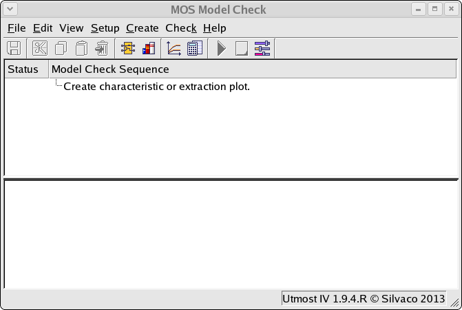
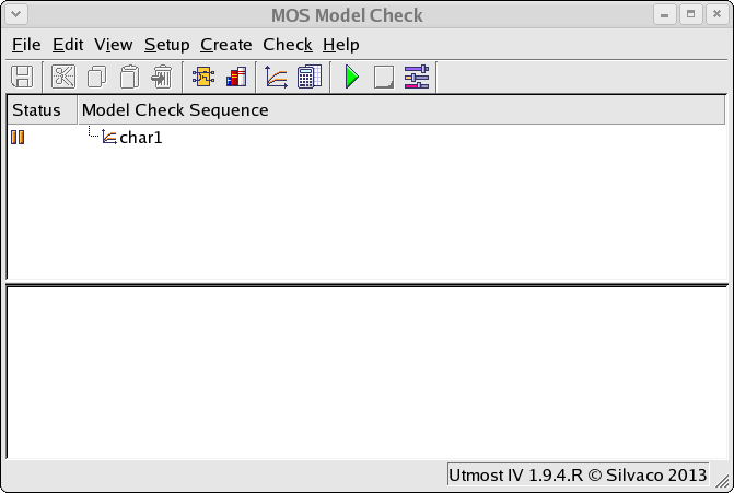
When the model check module window opens, it will appear as shown in check_ex01_01.png . From this window select File->Load and load the check_ex01.prj model check project. This will open the project for this example as shown in check_ex01_02.png .
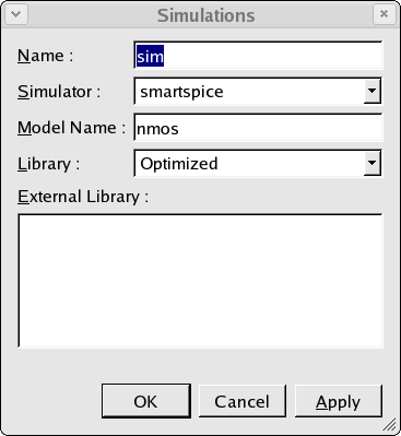
The first thing that must be done is to define the simulation that will be performed. Selecting Setup->Simulations will open the simulatino setup dialog as shown in check_ex01_03.png . Here the name of the model to be simulated is set. In this case the name is 'NMOS'. The setup also defines where where the model is located. The model can be loaded into the project as in this example, or in an external model library file.
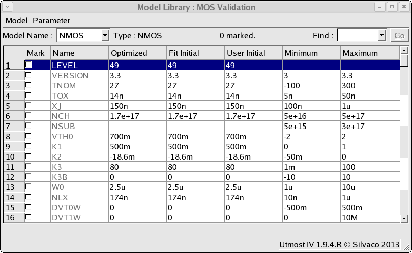
This example defines the model location to be in the model library, Selecting the Setup->Model Library menu item will open up the model library window as show in check_ex01_04.png . A single BSIM3 MOSFET model has been added to the model library with the name 'NMOS'in order to match the model name which was defined in the simulation setup.
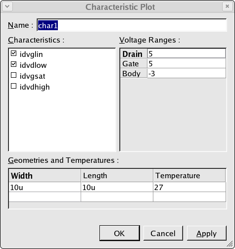
Now that the simulation is set up, a characteristic plot is created as shown in check_ex01_05.png . This allows the user to select which characteristics are to be plotted, the bias conditions for the simulations, the mosfet device width and length and finally the temperature for the simulations. The characteristic plot is automatically added into the model check sequence.
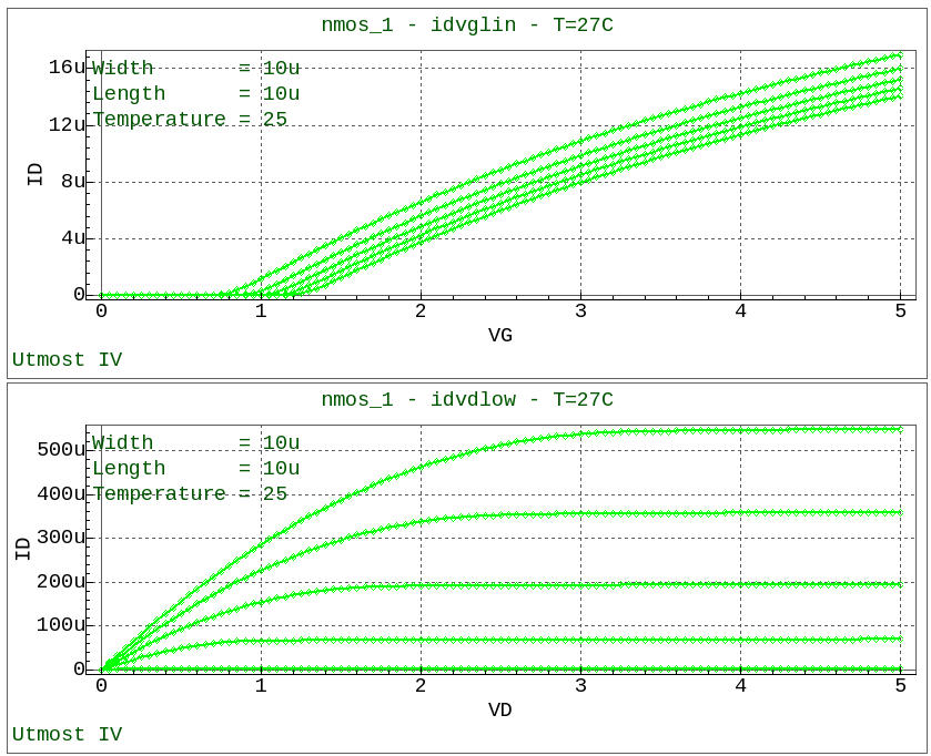
When the model check sequence is run, the desired characteristic plots are displayed in the viewer as shown in check_ex01_06.png .