opt_ex14 : HiSIM_HV2 VDMOS Model Extraction
Requires: Utmost IV, SmartSpice, SmartView
Minimum Versions: Utmost IV 1.10.6.R, SmartSpice 4.17.1.C, SmartView 2.28.2.R
This example demonstrates how to extract a standard HiSIM_HV2 model parameters for a single geometry Vdmos device. The datasets used are two drain current versus gate voltage characteristics at the low and the high drain voltages and one drain current versus the drain voltage characteristic. In addition, the capacitance data such as Cg_sdb, Cg_sb and Cgd are included.
The following process parameters are defined in the model library. The tox value is fixed during the optimization.
- tox:Physical oxide thickness
- nsubc:Substrate impurity concentration
- nover:Impurity concentration of loverld at drain, and at source if cosym=1 and the value is declared
Also, the following model parameter values can be set to reasonable starting values. They are then optimized through the optimization sequence.
- loverld:Overlap length at drain side, and at source if cosym=1
- lovers:Overlap length at source side
- ldrift1:Length of light doped drift region at drain, and at source if cosym=1
- ldrift2:Length of heavily doped drift region at drain side, and at source if cosym=1
Note: The model flag cosym=0 is used.
Even though the Vdmos structure is different from the Ldmos, the drift region is only in the drain side similar to the Ldmos.
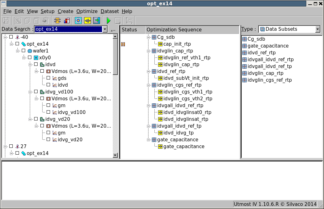
The project file opt_ex14.prj and the data file opt_ex14.uds for this example should be loaded into your database. When opened, the project will look as shown in opt_ex14_project.png .
The optimization sequence, which fully automates the extraction of HiSIM_HV2 model parameters, consists of seven sections. The section one is to get the initial estimate of the geometry correction terms. The section two extracts the threshold voltage region parameters. The third section is prepared to get the initial model parameters for the substrate current model. The section four aims to optimize the drift region resistance parameters at the low drain voltage. The bias dependency of the drift region resistance is optimized in the section five. And this completes the single geometry model parameters at the room temperature. The section six optimizes the temperature scaling model parameters to complete the HiSIM_HV2 DC model over the temperature change. The section seven is to get the gate capacitance characteristics.
Section 1 : Cg_sdb
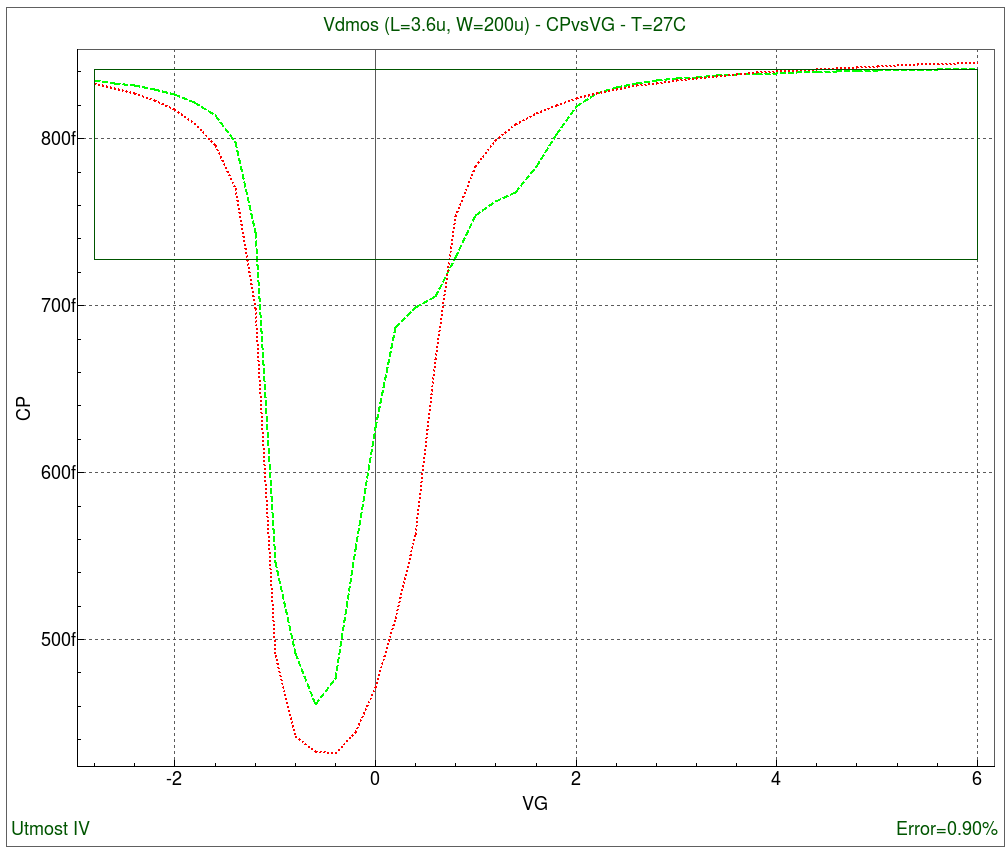
The first section is to estimate the drift region overlap length parameters and the channel width correction parameters of HiSIM_HV2 using the Cg_sdb (Cgg) capacitance characteristics. The following model parameters are extracted.
- loverld:Overlap length at drain side, and at source if cosym=1
- xldld:Gate overlap length at drain side
- xwd:Gate overlap width
After this section has been completed, the fit to measured data will be as shown in opt_ex14_01.png .
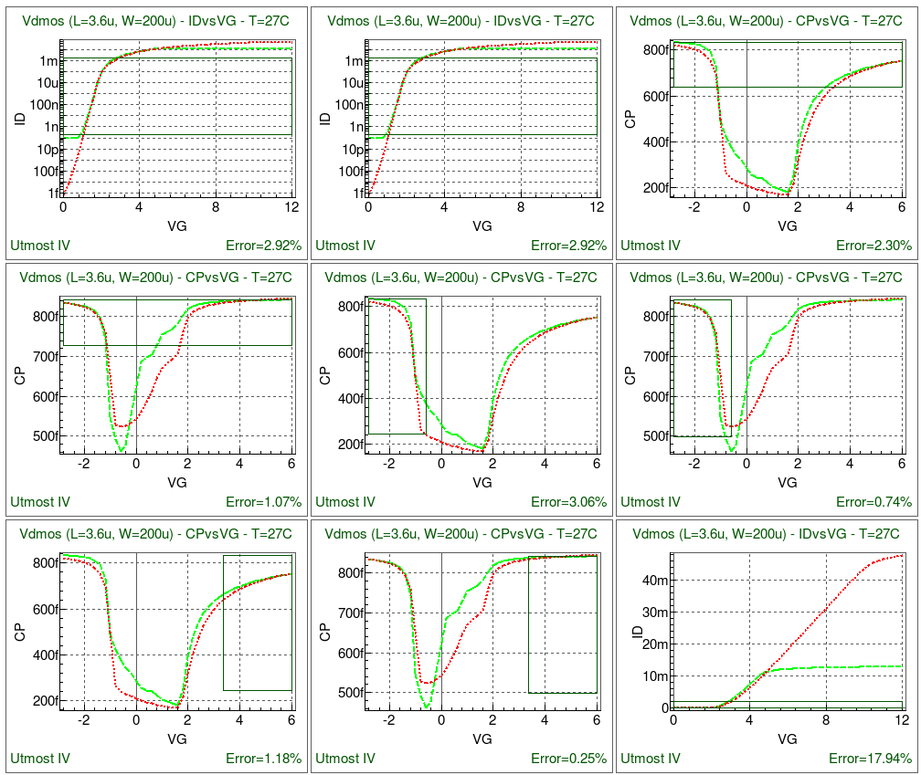
Section 2 : idvglin_cap_rtp
This section extracts the fundamental parameters for the Vdmos device. The data sets in this section are the drain current versus the gate voltage characteristic at the low drain voltage and the cg_sdb and cg_sb capacitance characteristics at the room temperature. The following model parameters are extracted.
- nsubc:Substrate impurity concentration
- vfbc:Flat band voltage
- muecb0:Coulomb scattering
- muecb1:Coulomb scattering
- mueph0:Phonon scattering
- mueph1:Phonon scattering
- ndep:Depletion charge contribution on effective electric field
- ninv:Inversion charge contribution on effective electric field
- vfbover:Flat-band voltage in overlap region
- nover:Impurity concentration of loverld at drain, and at source if cosym=1 and the value is declared
- ldrift1:Length of light doped drift region at drain, and at source if cosym=1
- ldrift2:Length of heavily doped drift region at drain side, and at source if cosym=1
- rdrdjunc:Junction depth at channel/drift region for cordrift=1
- rdrmue:Field dependent mobility in drift region for cordrift=1
After this section has been completed, the fit to measured data will be as shown in opt_ex14_02.png .
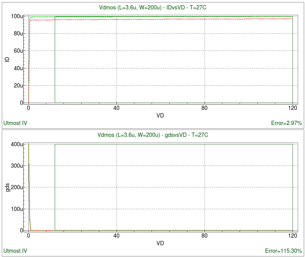
Section 3 : idvd_ref_rtp
The third section aims to obtain the initial values of the substrate current model and the channel length modulation parameters. The following model parameters are extracted.
- bb:High field mobility degradation
- sub1:Substrate current coefficient of magnitude
- sub2:Substrate current coefficient of exponential term
- svds:Substrate current coefficient of exponential term
- svgs:Substrate current dependence on vgs
- clm1:Hardness coefficient of channel/contact junction
- clm2:Coefficient of qb contribution
- clm3:Coefficient of qi contribution
- sc2:Vds dependence of short-channel effect
After this section has been completed, the fit to measured data will be as shown in opt_ex14_03.png .
Section 4 : idvglin_cgs_ref_rtp
This section extracts several parameters of the drift region resistance model. The data in this section is the drain current versus the gate voltage characteristic at the low drain voltage and the cg_sb capacitance versus the gate voltage. The cg_sb capacitance is used to observe the effect of the drift region resistance parameters. The following model parameters are extracted.
- rdrcx:Coefficient of current flow from xov for cordrift=1
- rdrdl1:Effective ldrift of current in drift region for cordrift=1
Also, the following model parameters used at the previous steps are included in this section to ensure the entire fitting.
- nsubc
- vfbc
- muecb0
- muecb1
- mueph0
- mueph1
- ninv
- ldrift1
- ldrift2
- rdrdjunc
- rdrmue
After this section has been completed, the fit to measured data will be as shown in opt_ex14_04.png .
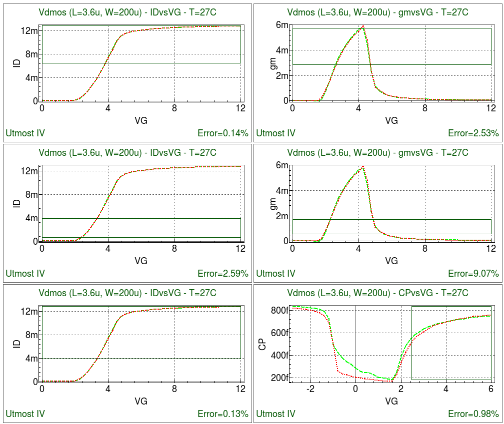
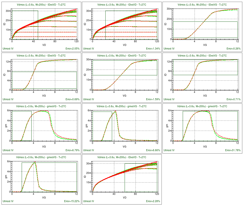
Section 5 : idvgall_idvd_ref_rtp
The previous four sections concentrated mostly on the drain current versus the gate voltage at the low drain voltage. The intention was to get the precise threshold model parameters. Also, the model parameters of the drift region resistance at the low drain voltage was extracted as the initial values for the succeeding optimization steps. This section will use the drain current versus the drain voltage data in addition to the drain current versus the gate voltage at the low and the high drain voltages to optimize the saturation region parameters and the drift resistance dependency on the drain and the gate voltages. The gate capacitances of cg_sdb and cg_sb are included to see the parameter effects. The following model parameters are extracted.
- ninvd:Reduced resistance effect for small Vds
- vmax:Saturation velocity
- vover:Velocity overshoot effect
- rdrcar:High field injection in drift region for cordrift=1
- rdrqover:Inclusion of the overlap change in rdrift for cordrift=1
- rdrvmax:Saturation velocity in drift region for cordrift=1
- rdrbb:High field mobility in drift region
- rth0:Thermal resistance
- subld1:Substrate current induced in ldrift model
- subld2:Substrate current induced in ldrift model
Also, the following model parameters used at the previous steps are included in this section to ensure the entire fitting.
- muecb0
- muecb1
- mueph0
- mueph1
- bb
- ninv
- ldrift1
- ldrift2
- rdrcx
- rdrdl1
- rdrdjunc
- rdrmue
- sub1
- sub2
- svds
- svgs
After this section has been completed, the fit to measured data will be as shown in opt_ex14_05.png .
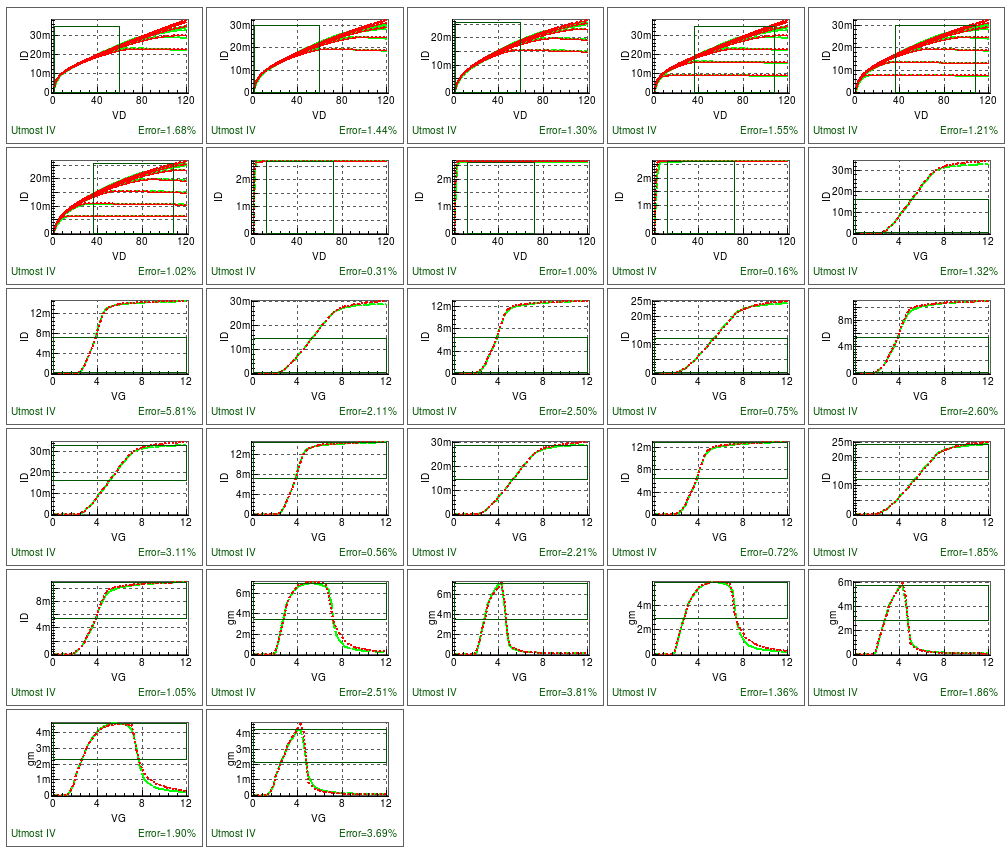
Section 6: idvgall_idvd_ref_tp
This section extracts the temperature model parameters using both the drain current versus the gate voltage and the drain current versus the drain voltage characteristics at three temperatures. The following model parameters are extracted.
- bgtmp1:Temperature dependence of bandgap
- bgtmp2:Temperature dependence of bandgap
- muetmp:Temperature dependence of phonon scattering
- vmaxt1:Temperature dependence of velocity
- vmaxt2:Temperature dependence of velocity
- vtmp:Temperature dependence of the saturation velocity
- rdrmuetmp:Temperature dependence of resistance for cordrift=1
- rdrvtmp:Temperature dependence of resistance for cordrift=1
- rthtemp1:Temperature dependence of thermal resistance
- rthtemp2:Temperature dependence of thermal resistance
Also, the following model parameters used at the previous steps are included in this section to ensure the entire fitting.
- bb
- rdrbb
After this section has been completed, the fit to measured data will be as shown in opt_ex14_06.png .
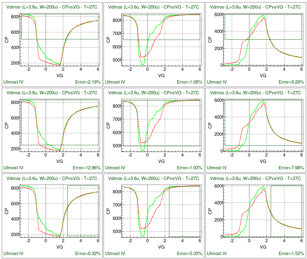
Section 7 : gate_capacitance
This section is to finalize the gate capacitance characteristic fitting. The following model parameters are extracted.
- xwdc:Gate overlap in width for capacitance calculation
- cvdsover:Parameter for cgg for vds =! 0
- cgso:Gate-to-source overlap capacitance
- cgdo:Gate-to-drain overlap capacitance
The parameters used in the previous section are the following;
- vfbover
- loverld
After this section has been completed, the fit to measured data will be as shown in opt_ex14_07.png .
The sequence is prepared for the best fit. No repeated run would be necessary. When complete, the model card can be exported into an external model library file as shown in the output file opt_ex14.lib.
Note for reducing the run time.
Utmost IV is able to control the number of parallel runs of SmartSpice. The increase of number of smartspice shortens the run time for the multi-core machines. Edit -> Preferences -> Simulator
opt_ex14.lib
											.MODEL HiSIM_HV2 NMOS (
+LEVEL    = 73             VERSION  = 2.1            coovlp   = 1
+coovlps  = 1              coisub   = 1              coiigs   = 0
+cogidl   = 0              coisti   = 0              coadov   = 1
+conqs    = 0              corg     = 0              corbnet  = 0
+coflick  = 0              cothrml  = 0              coign    = 0
+coiprv   = 1              copprv   = 1              codfm    = 0
+coselfheat = 1
+cotemp   = 0
+cosubnode = 0
+cosym    = 0              cordrift = 1              coqovsm  = 1
+coerrrep = 1              eg0      = 1.1785         bgtmp1   = 0.000247366
+bgtmp2   = -3.71827e-07   muetmp   = 1.73405        tnom     = 27
+vtmp     = 0.323045       vmaxt1   = 0.000444372    vmaxt2   = -7.96278e-07
+ninvdt1  = 0              ninvdt2  = 0              rthtemp1 = 4.53052e-05
+rthtemp2 = 0              tox      = 6e-08          xl       = 0
+xw       = 0              xld      = 0              xldld    = 1.23026e-06
+xwd      = 1.09086e-07    xwdld    = 0              xwdc     = -1e-08
+tpoly    = 2e-07          ll       = 0              lld      = 0
+lln      = 0              wl       = 0              wld      = 0
+wln      = 0              nsubc    = 4.69752e+16    nsubp    = 1e+18
+nsubsub  = 1e+15          lp       = 0              npext    = 5e+17
+lpext    = 1e-50          vfbc     = -1.12589       vbi      = 1.1
+kappa    = 3.9            ldrift1  = 1.27682e-07    ldrift2  = 1.30081e-07
+ldrift1s = 0              ldrift2s = 1e-06          ddrift   = 1e-06
+loverld  = 4.82849e-06    lovers   = 5e-08          vbsmin   = -10.5
+vgsmin   = -100           muecb0   = 100            muecb1   = 3645.09
+mueph0   = 0.25           mueph1   = 30000          muephl   = 0
+mueplp   = 1              muesr0   = 2              muesr1   = 8e+15
+muesrl   = 0              mueslp   = 1              ndep     = 0.560727
+ndepl    = 0              ndeplp   = 1              ninv     = 0.00976814
+ninvd    = 0              ninvdw   = 0              ninvdwp  = 1
+bb       = 1.82222        vmax     = 1.00668e+07    vover    = 0.302982
+voverp   = 0.3            rsh      = 0              rshg     = 0
+rbpb     = 50             rbpd     = 50             rbps     = 50
+rbdb     = 50             rbsb     = 50             rdrdl1   = 1.9985e-06
+rdrdl2   = 0              rdrcx    = 0.283434       rdrcar   = 5.37034e-09
+rdrdjunc = 5.44849e-07    rdrmue   = 100            rdrvmax  = 3.18072e+07
+rdrvmaxl = 0
+rdrvmaxlp = 1
+rdrvmaxw = 0
+rdrvmaxwp = 1
+rdrmuel  = 0              rdrmuelp = 1              rdrbb    = 0.957247
+rdrqover = 2804.71        rdrvtmp  = -0.218072
+rdrmuetmp = 1.60286
+gbmin    = 1e-12          rth0     = 0.303333       cth0     = 1e-07
+rth0w    = 0              rth0wp   = 1              rth0nf   = 0
+powrat   = 1
+prattemp1 = 0
+prattemp2 = 0
+shemax   = 500            nfalp    = 1e-19          nftrp    = 1e+10
+cit      = 0              falph    = 1              sub1     = 0.001
+sub1l    = 0.0025         sub1lp   = 1              sub2     = 250
+sub2l    = 2e-06          svds     = 0.2            slg      = 3e-08
+slgl     = 0              slglp    = 1              svbs     = 0.5
+svbsl    = 0              svbslp   = 1              svgs     = 0.7
+svgsl    = 0              svgslp   = 1              svgsw    = 0
+svgswp   = 1              ibpc1    = 0              ibpc2    = 0
+ibpc1l   = 0              ibpc1lp  = -1             subld1   = 9.51834e-06
+subld2   = 2.91716e-09    subld1l  = 0              subld1lp = 1
+xpdv     = 0              xpvdth   = 0              xpvdthg  = 0
+mphdfm   = -0.3           parl2    = 1e-08          sc1      = 0
+sc2      = 0              sc3      = 0              sc4      = 0
+scp1     = 0              scp2     = 0              scp3     = 0
+scp21    = 0              bs1      = 0              bs2      = 0.9
+clm1     = 0.0100504      clm2     = 3.99949        clm3     = 4.99987
+clm5     = 1              clm6     = 0              wfc      = 0
+wvth0    = 0              nsubcw   = 0              nsubcwp  = 1
+nsubp0   = 0              nsubwp   = 1              muephw   = 0
+muepwp   = 1              muesrw   = 0              mueswp   = 1
+vthsti   = 0              vdsti    = 0              scsti1   = 0
+scsti2   = 0              nsti     = 1e+16          wsti     = 0
+wstil    = 0              wstilp   = 1              wstiw    = 0
+wstiwp   = 1              wl1      = 0              wl1p     = 1
+nsubpsti1 = 0
+nsubpsti2 = 0
+nsubpsti3 = 1
+muesti1  = 0              muesti2  = 0              muesti3  = 1
+saref    = 1e-06          sbref    = 1e-06          wl2      = 0
+wl2p     = 1              muephs   = 0              muepsp   = 1
+vovers   = 0              voversp  = 0              qme1     = 0
+qme2     = 2              qme3     = 0              pgd1     = 0
+pgd2     = 1              pgd4     = 0              gleak1   = 50
+gleak2   = 1e+07          gleak3   = 0.06           gleak4   = 4
+gleak5   = 7500           gleak6   = 0.25           gleak7   = 1e-06
+egig     = 0              igtemp2  = 0              igtemp3  = 0
+glksd1   = 1e-15          glksd2   = 1000           glksd3   = -1000
+glkb1    = 5e-16          glkb2    = 1              glkb3    = 0
+glpart1  = 0.5            fn1      = 50             fn2      = 0.00017
+fn3      = 0              fvbs     = 0.012          gidl1    = 2
+gidl2    = 3e+07          gidl3    = 0.9            gidl4    = 0
+gidl5    = 0.2            vzadd0   = 0.01           pzadd0   = 0.005
+ddltmax  = 10             ddltslp  = 0              ddltict  = 10
+js0      = 5e-07          js0sw    = 0              nj       = 1
+njsw     = 1              xti      = 2              xti2     = 0
+divx     = 0              ctemp    = 0              cisb     = 0
+cisbk    = 0              cvb      = 0              cj       = 0.0005
+cjsw     = 5e-10          cjswg    = 5e-10          mj       = 0.5
+mjsw     = 0.33           mjswg    = 0.33           pb       = 1
+pbsw     = 1              pbswg    = 1              vdiffj   = 0.0006
+tcjbd    = 0              tcjbdsw  = 0              tcjbdswg = 0
+tcjbs    = 0              tcjbssw  = 0              tcjbsswg = 0
+xqy      = 0              xqy1     = 0              xqy2     = 2
+nover    = 1.95762e+16    vfbover  = -0.993669      qovadd   = 0
+novers   = 1e+16          ovslp    = 2.1e-07        ovmag    = 0.6
+cgso     = 2.34797e-11    cgdo     = 1.8984e-11     cgbo     = 0
+cvdsover = 0.0475194      dly1     = 1e-10          dly2     = 0.7
+dly3     = 8e-07          pt2      = 0              pt4      = 0
+pt4p     = 1              ptl      = 0              ptlp     = 1
+ptp      = 3.5            gdl      = 0              gdld     = 0
+gdlp     = 0              gdsleak  = 0              lbinn    = 1
+wbinn    = 1              lmax     = 1              lmin     = 0
+wmax     = 1              wmin     = 0 )
opt_ex14.uds
Utmost IV CSV Data Logfile Format Version 1 Copyright (c) 1984-2016 Silvaco, Inc. All rights reserved DataSetStart DataSetName, idvd MeasurementType, DC BatchName, opt_ex14 WaferName, wafer1 DieName, x0y0 DeviceName, Vdmos Temperature, -40 CustomerName, Silvaco ProductName, HiSIM_HV2example_for_Vdmos FabDate, 26 Nov 2013 UserDate, 26 Nov 2013 WaferDiameter, 0.2 DieLayout, FOUR_CROSSING DieSize, 0.02, 0.02 Attribute, L, 3.6e-06 Attribute, W, 0.0002 NodeNames, d g s b Sweep, 1, V, D, LIN, 0, 120, 0.5, CALCULATED, 0.1, 0 Sweep, 2, V, G, LIN, 2, 10, 1, CALCULATED, 0.1, 0.0 Constant, V, S B, 0, 0.1, 0 Target, I, D Function, gds, derivative(vd, id) Plot, idvd, XY (LIN LIN), vd, id Plot, gds, XY (LIN LOG), vd, gds DataArray, ID 3.10035e-18 6.43583e-06 6.45487e-06 6.45674e-06 6.45758e-06 6.45781e-06 6.45799e-06 6.45814e-06 6.45827e-06 6.45838e-06 6.45849e-06 6.45859e-06 6.45868e-06 6.45877e-06 6.45885e-06 6.45893e-06 6.45901e-06 6.45909e-06 6.45916e-06 6.45923e-06 6.4593e-06 6.45937e-06 6.45944e-06 6.4595e-06 6.45957e-06 6.45963e-06 6.4597e-06 6.45976e-06 6.45983e-06 6.45989e-06 6.45995e-06 6.46001e-06 6.46007e-06 6.46013e-06 6.46019e-06 6.46025e-06 6.46031e-06 6.46036e-06 6.46042e-06 6.46048e-06 6.46054e-06 6.46059e-06 6.46065e-06 6.46071e-06 6.46077e-06 6.46082e-06 6.46088e-06 6.46093e-06 6.46099e-06 6.46104e-06 6.4611e-06 6.46115e-06 6.46121e-06 6.46126e-06 6.46131e-06 6.46137e-06 6.46142e-06 6.46148e-06 6.46153e-06 6.46158e-06 6.46164e-06 6.46169e-06 6.46175e-06 6.4618e-06 6.46186e-06 6.46191e-06 6.46197e-06 6.46203e-06 6.46208e-06 6.46214e-06 6.46219e-06 6.46225e-06 6.4623e-06 6.46236e-06 6.46241e-06 6.46247e-06 6.46252e-06 6.46258e-06 6.46264e-06 6.46269e-06 6.46275e-06 6.4628e-06 6.46286e-06 6.46291e-06 6.46297e-06 6.46302e-06 6.46308e-06 6.46313e-06 6.46319e-06 6.46324e-06 6.4633e-06 6.46335e-06 6.46341e-06 6.46346e-06 6.46351e-06 6.46357e-06 6.46362e-06 6.46368e-06 6.46373e-06 6.46378e-06 6.46384e-06 6.46389e-06 6.46394e-06 6.46399e-06 6.46405e-06 6.4641e-06 6.46415e-06 6.46421e-06 6.46426e-06 6.46431e-06 6.46436e-06 6.46442e-06 6.46447e-06 6.46452e-06 6.46458e-06 6.46463e-06 6.46468e-06 6.46474e-06 6.46479e-06 6.46484e-06 6.4649e-06 6.46495e-06 6.46501e-06 6.46506e-06 6.46512e-06 6.46517e-06 6.46523e-06 6.46528e-06 6.46534e-06 6.46539e-06 6.46545e-06 6.4655e-06 6.46556e-06 6.46561e-06 6.46567e-06 6.46572e-06 6.46578e-06 6.46583e-06 6.46589e-06 6.46594e-06 6.466e-06 6.46606e-06 6.46611e-06 6.46617e-06 6.46622e-06 6.46628e-06 6.46633e-06 6.46639e-06 6.46645e-06 6.4665e-06 6.46656e-06 6.46661e-06 6.46667e-06 6.46673e-06 6.46678e-06 6.46684e-06 6.4669e-06 6.46695e-06 6.46701e-06 6.46707e-06 6.46712e-06 6.46718e-06 6.46724e-06 6.46729e-06 6.46735e-06 6.46741e-06 6.46746e-06 6.46752e-06 6.46758e-06 6.46763e-06 6.46769e-06 6.46775e-06 6.4678e-06 6.46786e-06 6.46792e-06 6.46797e-06 6.46803e-06 6.46809e-06 6.46814e-06 6.4682e-06 6.46826e-06 6.46832e-06 6.46837e-06 6.46843e-06 6.46849e-06 6.46854e-06 6.4686e-06 6.46866e-06 6.46871e-06 6.46877e-06 6.46883e-06 6.46889e-06 6.46894e-06 6.469e-06 6.46906e-06 6.46912e-06 6.46918e-06 6.46923e-06 6.46929e-06 6.46935e-06 6.46941e-06 6.46947e-06 6.46953e-06 6.46959e-06 6.46964e-06 6.4697e-06 6.46976e-06 6.46982e-06 6.46988e-06 6.46994e-06 6.46999e-06 6.47005e-06 6.47011e-06 6.47017e-06 6.47023e-06 6.47029e-06 6.47035e-06 6.47041e-06 6.47046e-06 6.47052e-06 6.47058e-06 6.47064e-06 6.4707e-06 6.47076e-06 6.47082e-06 6.47087e-06 6.47093e-06 6.47099e-06 6.47105e-06 6.47111e-06 6.47117e-06 6.47122e-06 6.47128e-06 6.47134e-06 6.4714e-06 6.47145e-06 6.47151e-06 6.47157e-06 6.47163e-06 6.47169e-06 6.47174e-06 3.10035e-18 0.000908947 0.00164827 0.00218679 0.0024978 0.00262475 0.00266394 0.00267655 0.00268131 0.0026831 0.00268378 0.0026841 0.00268431 0.00268446 0.00268458 0.00268468 0.00268476 0.00268482 0.00268487 0.00268491 0.00268494 0.00268497 0.00268499 0.002685 0.00268501 0.00268502 0.00268503 0.00268503 0.00268503 0.00268503 0.00268503 0.00268502 0.00268501 0.002685 0.00268499 0.00268498 0.00268496 0.00268495 0.00268493 0.00268491 0.00268489 0.00268487 0.00268485 0.00268483 0.00268481 0.00268478 0.00268476 0.00268473 0.00268471 0.00268468 0.00268466 0.00268463 0.00268461 0.00268459 0.00268456 0.00268454 0.00268452 0.00268451 0.00268449 0.00268448 0.00268447 0.00268447 0.00268446 0.00268446 0.00268446 0.00268447 0.00268447 0.00268448 0.00268448 0.00268449 0.00268449 0.0026845 0.00268451 0.00268451 0.00268451 0.00268452 0.00268452 0.00268452 0.00268452 0.00268452 0.00268452 0.00268452 0.00268451 0.0026845 0.00268449 0.00268448 0.00268447 0.00268445 0.00268443 0.00268441 0.00268439 0.00268436 0.00268434 0.00268431 0.00268428 0.00268425 0.00268422 0.00268418 0.00268415 0.00268411 0.00268408 0.00268404 0.002684 0.00268396 0.00268392 0.00268388 0.00268384 0.0026838 0.00268376 0.00268372 0.00268368 0.00268364 0.00268359 0.00268355 0.00268351 0.00268347 0.00268342 0.00268338 0.00268334 0.00268329 0.00268325 0.00268321 0.00268316 0.00268312 0.00268308 0.00268304 0.002683 0.00268295 0.00268291 0.00268287 0.00268283 0.00268279 0.00268275 0.00268271 0.00268267 0.00268263 0.00268259 0.00268255 0.00268251 0.00268247 0.00268243 0.00268239 0.00268235 0.00268231 0.00268227 0.00268223 0.00268219 0.00268215 0.00268211 0.00268207 0.00268203 0.00268199 0.00268195 0.00268191 0.00268187 0.00268183 0.00268179 0.00268175 0.00268171 0.00268167 0.00268163 0.0026816 0.00268156 0.00268152 0.00268148 0.00268144 0.0026814 0.00268136 0.00268133 0.00268129 0.00268125 0.00268121 0.00268117 0.00268113 0.00268109 0.00268105 0.00268102 0.00268098 0.00268094 0.0026809 0.00268086 0.00268082 0.00268079 0.00268075 0.00268071 0.00268067 0.00268063 0.0026806 0.00268056 0.00268052 0.00268048 0.00268045 0.00268041 0.00268037 0.00268034 0.0026803 0.00268027 0.00268023 0.0026802 0.00268016 0.00268013 0.0026801 0.00268006 0.00268003 0.00268 0.00267996 0.00267993 0.0026799 0.00267986 0.00267983 0.0026798 0.00267976 0.00267973 0.0026797 0.00267967 0.00267964 0.0026796 0.00267957 0.00267954 0.00267951 0.00267948 0.00267944 0.00267941 0.00267938 0.00267935 0.00267932 0.00267928 0.00267925 0.00267922 0.00267919 0.00267915 0.00267912 0.00267909 0.00267906 0.00267903 0.002679 0.00267896 0.00267893 0.0026789 0.00267887 0.00267884 1.54801e-38 0.00113123 0.00217146 0.00310887 0.00393808 0.00466155 0.00528695 0.00582454 0.00628388 0.00667752 0.00701782 0.00731373 0.00757214 0.00779912 0.00799892 0.00817421 0.00832669 0.00845772 0.00856788 0.00865765 0.00872838 0.00878231 0.00882226 0.00885121 0.00887183 0.0088863 0.00889624 0.00890266 0.00890592 0.00890727 0.00890785 0.00890803 0.00890791 0.00890755 0.00890697 0.00890616 0.00890516 0.00890401 0.00890274 0.00890139 0.00889997 0.00889851 0.00889701 0.00889549 0.00889394 0.00889238 0.0088908 0.0088892 0.0088876 0.00888598 0.00888436 0.00888272 0.00888107 0.00887942 0.00887776 0.0088761 0.00887442 0.00887275 0.00887106 0.00886937 0.00886768 0.00886598 0.00886427 0.00886256 0.00886085 0.00885914 0.00885743 0.00885572 0.00885401 0.0088523 0.00885059 0.00884888 0.00884717 0.00884547 0.00884379 0.00884211 0.00884045 0.0088388 0.00883717 0.00883555 0.00883394 0.00883235 0.00883078 0.00882922 0.00882768 0.00882616 0.00882465 0.00882315 0.00882167 0.00882019 0.00881873 0.00881727 0.00881582 0.00881438 0.00881294 0.00881151 0.00881007 0.00880864 0.00880722 0.00880579 0.00880437 0.00880294 0.00880152 0.00880009 0.00879867 0.00879724 0.00879582 0.00879439 0.00879296 0.00879152 0.00879009 0.00878865 0.00878721 0.00878577 0.00878432 0.00878287 0.00878142 0.00877997 0.00877851 0.00877705 0.00877559 0.00877412 0.00877265 0.00877118 0.0087697 0.00876822 0.00876674 0.00876526 0.00876377 0.00876228 0.00876078 0.00875929 0.00875779 0.00875629 0.00875478 0.00875328 0.00875178 0.00875028 0.00874878 0.00874727 0.00874577 0.00874427 0.00874276 0.00874124 0.00873972 0.00873819 0.00873666 0.00873512 0.00873357 0.00873202 0.00873046 0.00872889 0.00872731 0.00872573 0.00872414 0.00872254 0.00872094 0.00871932 0.0087177 0.00871607 0.00871444 0.0087128 0.00871116 0.00870951 0.00870785 0.00870619 0.00870451 0.00870283 0.00870115 0.00869945 0.00869776 0.00869605 0.00869434 0.00869263 0.00869091 0.00868919 0.00868746 0.00868573 0.008684 0.00868227 0.00868053 0.00867879 0.00867705 0.0086753 0.00867356 0.00867182 0.00867007 0.00866832 0.00866658 0.00866483 0.00866308 0.00866133 0.00865958 0.00865783 0.00865608 0.00865433 0.00865258 0.00865083 0.00864907 0.00864732 0.00864557 0.00864382 0.00864207 0.00864032 0.00863858 0.00863683 0.00863508 0.00863334 0.00863159 0.00862985 0.00862811 0.00862638 0.00862464 0.00862291 0.00862117 0.00861944 0.00861771 0.00861597 0.00861424 0.0086125 0.00861077 0.00860903 0.0086073 0.00860556 0.00860383 0.00860209 0.00860035 0.00859862 0.00859688 0.00859515 0.00859341 0.00859168 0.00858994 0.0085882 0.00858647 0.00858473 0.008583 0.00858127 0.00857953 0.0085778 0.00857606 4.0794e-18 0.00122704 0.00236524 0.00339529 0.00430598 0.00509591 0.00577336 0.00635359 0.0068513 0.00728181 0.00765998 0.00799788 0.00830373 0.00858446 0.00884518 0.00908953 0.00932037 0.00954032 0.0097515 0.00995457 0.0101501 0.010339 0.0105224 0.010701 0.0108755 0.0110466 0.0112146 0.0113799 0.0115428 0.0117033 0.0118616 0.0120178 0.0121718 0.0123238 0.0124737 0.0126215 0.0127672 0.0129108 0.0130522 0.0131915 0.0133288 0.0134639 0.0135967 0.013727 0.0138546 0.0139795 0.0141015 0.0142206 0.0143366 0.0144497 0.01456 0.0146675 0.0147722 0.0148742 0.0149734 0.0150697 0.0151631 0.0152534 0.0153404 0.0154239 0.0155037 0.0155796 0.0156514 0.0157188 0.0157816 0.0158396 0.0158926 0.0159407 0.0159837 0.0160219 0.0160552 0.0160839 0.0161084 0.0161288 0.0161456 0.016159 0.0161692 0.0161766 0.0161811 0.0161828 0.016182 0.0161798 0.0161768 0.0161735 0.0161698 0.0161659 0.0161618 0.0161576 0.0161532 0.0161486 0.016144 0.0161392 0.0161342 0.0161291 0.0161238 0.0161184 0.0161129 0.0161072 0.0161014 0.0160956 0.0160896 0.0160837 0.0160777 0.0160716 0.0160656 0.0160595 0.0160535 0.0160474 0.0160414 0.0160354 0.0160295 0.0160236 0.0160177 0.0160118 0.016006 0.0160003 0.0159945 0.0159888 0.0159832 0.0159775 0.0159719 0.0159663 0.0159607 0.0159551 0.0159496 0.015944 0.0159385 0.015933 0.0159274 0.0159219 0.0159164 0.0159109 0.0159054 0.0158999 0.0158944 0.0158888 0.0158833 0.0158778 0.0158723 0.0158668 0.0158613 0.0158557 0.0158502 0.0158447 0.0158392 0.0158337 0.0158281 0.0158226 0.0158171 0.0158116 0.015806 0.0158005 0.015795 0.0157895 0.0157839 0.0157784 0.0157729 0.0157673 0.0157618 0.0157562 0.0157507 0.0157451 0.0157395 0.0157339 0.0157283 0.0157227 0.0157171 0.0157115 0.0157059 0.0157003 0.0156946 0.015689 0.0156834 0.0156778 0.0156721 0.0156665 0.0156608 0.0156552 0.0156495 0.0156438 0.0156381 0.0156324 0.0156267 0.015621 0.0156153 0.0156096 0.0156038 0.0155981 0.0155923 0.0155866 0.0155808 0.015575 0.0155693 0.0155635 0.0155577 0.0155519 0.0155461 0.0155403 0.0155345 0.0155286 0.0155228 0.015517 0.0155111 0.0155053 0.0154994 0.0154936 0.0154877 0.0154819 0.015476 0.0154701 0.0154643 0.0154584 0.0154525 0.0154466 0.0154407 0.0154349 0.015429 0.0154231 0.0154172 0.0154113 0.0154054 0.0153995 0.0153935 0.0153876 0.0153817 0.0153758 0.0153699 0.0153639 0.015358 0.0153521 0.0153462 0.0153402 0.0153343 0.0153284 0.0153224 0.0153165 0.0153105 0.0153046 0.0152986 0.0152926 0.0152867 4.0794e-18 0.00128374 0.00247461 0.00354874 0.00449245 0.00530376 0.00599297 0.00657877 0.00707945 0.00751229 0.00789277 0.00823362 0.00854352 0.00882911 0.00909526 0.00934546 0.00958241 0.00980863 0.0100263 0.0102362 0.010439 0.0106356 0.0108271 0.0110142 0.0111978 0.0113782 0.0115561 0.0117316 0.0119049 0.0120764 0.0122459 0.0124136 0.0125796 0.0127439 0.0129065 0.0130674 0.0132265 0.0133838 0.0135392 0.0136927 0.0138442 0.0139936 0.0141411 0.0142867 0.0144307 0.0145729 0.0147133 0.0148518 0.0149885 0.0151234 0.0152568 0.0153889 0.0155199 0.0156497 0.0157787 0.0159069 0.0160342 0.0161608 0.0162867 0.0164119 0.0165365 0.0166604 0.0167838 0.0169066 0.0170288 0.0171504 0.0172714 0.0173919 0.0175118 0.0176312 0.0177501 0.0178684 0.0179863 0.0181037 0.0182207 0.0183374 0.0184536 0.0185696 0.0186854 0.0188008 0.0189157 0.0190299 0.0191434 0.0192562 0.0193683 0.0194796 0.0195902 0.0197 0.019809 0.0199172 0.0200246 0.0201312 0.0202369 0.0203417 0.0204457 0.0205488 0.0206508 0.0207519 0.020852 0.020951 0.0210489 0.0211457 0.0212414 0.021336 0.0214295 0.0215219 0.0216131 0.0217029 0.0217911 0.0218777 0.0219625 0.0220454 0.0221263 0.0222051 0.0222816 0.0223558 0.0224276 0.0224967 0.0225631 0.0226266 0.0226871 0.0227445 0.0227985 0.0228491 0.0228962 0.0229396 0.0229793 0.0230152 0.0230474 0.0230758 0.0231006 0.0231218 0.0231396 0.0231542 0.0231657 0.0231744 0.0231803 0.0231835 0.0231839 0.0231815 0.0231765 0.0231696 0.0231618 0.0231534 0.0231446 0.0231356 0.0231264 0.0231171 0.0231076 0.023098 0.0230882 0.0230784 0.0230684 0.0230583 0.0230481 0.0230377 0.0230272 0.0230166 0.0230057 0.0229948 0.0229836 0.0229723 0.0229609 0.0229494 0.0229378 0.0229261 0.0229144 0.0229026 0.0228908 0.0228789 0.0228671 0.0228552 0.0228433 0.0228313 0.0228194 0.0228074 0.0227954 0.0227834 0.0227714 0.0227594 0.0227473 0.0227353 0.0227233 0.0227112 0.0226992 0.0226872 0.0226751 0.0226631 0.022651 0.022639 0.0226269 0.0226148 0.0226027 0.0225907 0.0225786 0.0225665 0.0225544 0.0225423 0.0225302 0.0225181 0.0225059 0.0224938 0.0224817 0.0224696 0.0224575 0.0224453 0.0224332 0.0224211 0.0224089 0.0223968 0.0223847 0.0223725 0.0223604 0.0223483 0.0223361 0.022324 0.0223119 0.0222997 0.0222876 0.0222755 0.0222633 0.0222512 0.0222391 0.022227 0.0222149 0.0222027 0.0221906 0.0221785 0.0221664 0.0221543 0.0221422 0.0221301 0.0221179 0.0221058 0.0220937 0.0220816 0.0220696 0.0220575 0.0220454 0.0220333 0.0220212 3.10035e-18 0.00132194 0.0025466 0.00364718 0.00460902 0.00543057 0.00612415 0.00671086 0.00721116 0.0076436 0.00802398 0.00836522 0.00867619 0.00896335 0.00923138 0.00948364 0.00972277 0.00995119 0.0101711 0.0103835 0.0105889 0.0107883 0.0109827 0.0111729 0.0113597 0.0115435 0.0117247 0.0119037 0.0120806 0.0122556 0.0124287 0.0126001 0.0127698 0.0129378 0.0131041 0.0132686 0.0134313 0.0135922 0.0137512 0.0139081 0.014063 0.0142156 0.014366 0.0145145 0.0146613 0.0148065 0.0149501 0.0150921 0.0152325 0.0153713 0.0155088 0.015645 0.0157803 0.0159146 0.0160481 0.0161809 0.0163131 0.0164446 0.0165756 0.0167059 0.0168358 0.0169652 0.0170941 0.0172226 0.0173507 0.0174783 0.0176055 0.0177322 0.0178586 0.0179846 0.0181103 0.0182356 0.0183606 0.0184854 0.0186099 0.0187343 0.0188585 0.0189826 0.0191067 0.0192308 0.0193549 0.0194788 0.0196023 0.0197254 0.0198482 0.0199706 0.0200927 0.0202144 0.0203357 0.0204567 0.0205773 0.0206976 0.0208175 0.0209371 0.0210565 0.0211754 0.0212941 0.0214124 0.0215303 0.0216479 0.0217651 0.0218818 0.0219983 0.0221143 0.0222299 0.0223453 0.0224602 0.0225749 0.0226893 0.0228036 0.0229177 0.0230316 0.0231454 0.0232588 0.0233718 0.0234843 0.0235963 0.0237076 0.0238184 0.0239285 0.0240379 0.0241467 0.0242548 0.0243622 0.0244688 0.0245748 0.02468 0.0247845 0.0248882 0.0249911 0.0250932 0.0251945 0.0252949 0.0253944 0.0254929 0.0255906 0.0256872 0.0257829 0.0258775 0.0259712 0.0260637 0.0261553 0.0262457 0.0263349 0.0264231 0.02651 0.0265957 0.0266802 0.0267634 0.0268453 0.0269258 0.0270049 0.0270826 0.0271588 0.0272336 0.027307 0.0273789 0.0274494 0.0275186 0.0275863 0.0276527 0.0277175 0.0277809 0.0278429 0.0279034 0.0279625 0.0280201 0.0280763 0.0281311 0.0281844 0.0282364 0.0282869 0.028336 0.0283836 0.0284298 0.0284744 0.0285176 0.0285593 0.0285994 0.0286379 0.0286748 0.0287102 0.0287439 0.0287759 0.0288063 0.0288351 0.0288621 0.0288874 0.028911 0.0289329 0.0289531 0.0289716 0.0289884 0.0290036 0.029017 0.0290288 0.0290388 0.0290471 0.0290537 0.0290583 0.0290611 0.0290617 0.0290601 0.0290558 0.0290488 0.0290393 0.0290278 0.029015 0.0290013 0.028987 0.0289723 0.0289573 0.028942 0.0289264 0.0289107 0.0288948 0.0288787 0.0288624 0.028846 0.0288294 0.0288126 0.0287957 0.0287787 0.0287615 0.0287441 0.0287266 0.0287089 0.0286911 0.028673 0.0286548 0.0286365 0.0286179 0.0285993 0.0285805 0.0285615 0.0285425 0.0285233 0.0285041 0.0284848 0.0284655 0.0284461 4.0794e-18 0.00134967 0.00259813 0.00371657 0.00468995 0.00551742 0.006213 0.00679958 0.00729899 0.00773065 0.00811059 0.00845174 0.00876312 0.00905104 0.00932004 0.00957337 0.00981365 0.0100432 0.0102643 0.010478 0.0106848 0.0108857 0.0110818 0.0112737 0.0114623 0.0116479 0.011831 0.0120118 0.0121907 0.0123676 0.0125427 0.012716 0.0128876 0.0130575 0.0132256 0.0133921 0.0135566 0.0137193 0.01388 0.0140387 0.0141951 0.0143492 0.0145011 0.0146509 0.0147989 0.0149453 0.0150904 0.015234 0.0153761 0.0155168 0.0156562 0.0157945 0.0159318 0.0160682 0.0162039 0.0163389 0.0164733 0.0166072 0.0167405 0.0168732 0.0170055 0.0171374 0.0172688 0.0173998 0.0175305 0.0176607 0.0177906 0.0179201 0.0180493 0.0181782 0.0183069 0.0184352 0.0185633 0.0186913 0.0188191 0.0189469 0.0190746 0.0192022 0.0193299 0.0194577 0.0195857 0.0197137 0.0198416 0.0199692 0.0200966 0.0202238 0.0203507 0.0204774 0.0206039 0.0207302 0.0208562 0.020982 0.0211076 0.021233 0.0213581 0.0214831 0.0216079 0.0217324 0.0218566 0.0219806 0.0221042 0.0222276 0.0223507 0.0224735 0.022596 0.0227182 0.02284 0.0229616 0.023083 0.0232041 0.023325 0.0234458 0.0235665 0.0236871 0.0238077 0.023928 0.0240481 0.0241679 0.0242872 0.024406 0.0245243 0.0246421 0.0247594 0.024876 0.0249921 0.0251077 0.0252226 0.0253369 0.0254507 0.0255638 0.0256762 0.025788 0.0258991 0.0260094 0.0261191 0.0262279 0.026336 0.0264433 0.0265497 0.0266553 0.0267601 0.026864 0.026967 0.0270691 0.0271703 0.0272705 0.0273696 0.0274677 0.0275648 0.0276607 0.0277555 0.0278491 0.0279415 0.0280326 0.0281225 0.0282112 0.0282988 0.0283852 0.0284706 0.0285549 0.0286382 0.0287206 0.028802 0.0288825 0.028962 0.0290406 0.0291183 0.0291951 0.0292711 0.0293463 0.0294207 0.0294943 0.0295672 0.0296394 0.0297108 0.0297815 0.0298515 0.0299208 0.0299893 0.0300572 0.0301243 0.0301908 0.0302565 0.0303216 0.030386 0.0304497 0.0305127 0.030575 0.0306366 0.0306975 0.0307578 0.0308174 0.0308763 0.0309345 0.0309921 0.031049 0.0311052 0.0311607 0.0312156 0.0312699 0.0313235 0.0313765 0.0314288 0.0314805 0.0315315 0.0315819 0.0316318 0.0316811 0.0317298 0.031778 0.0318258 0.031873 0.0319196 0.0319657 0.0320111 0.032056 0.0321002 0.0321437 0.0321865 0.0322286 0.03227 0.0323105 0.0323503 0.0323893 0.0324275 0.0324649 0.0325014 0.0325372 0.0325721 0.0326061 0.0326393 0.0326717 0.0327032 0.0327339 0.0327637 0.0327927 0.0328208 0.032848 0.0328744 0.0328998 0.0329244 4.0794e-18 0.00137081 0.00263706 0.00376846 0.00474987 0.00558116 0.00627777 0.00686394 0.00736248 0.00779339 0.00817286 0.00851382 0.00882539 0.00911376 0.00938334 0.00963735 0.00987836 0.0101087 0.0103305 0.010545 0.0107528 0.0109547 0.0111518 0.0113449 0.0115346 0.0117214 0.0119057 0.0120878 0.0122678 0.012446 0.0126223 0.0127969 0.0129698 0.0131409 0.0133103 0.0134779 0.0136437 0.0138075 0.0139693 0.014129 0.0142864 0.0144415 0.0145943 0.014745 0.0148937 0.0150409 0.0151867 0.0153313 0.0154745 0.0156164 0.015757 0.0158965 0.0160351 0.0161728 0.0163099 0.0164463 0.016582 0.0167173 0.016852 0.0169862 0.01712 0.0172534 0.0173863 0.017519 0.0176512 0.0177832 0.0179147 0.018046 0.0181771 0.0183078 0.0184384 0.0185688 0.018699 0.018829 0.0189591 0.0190891 0.0192192 0.0193492 0.0194793 0.0196095 0.0197401 0.0198708 0.0200015 0.0201321 0.0202625 0.0203927 0.0205228 0.0206527 0.0207824 0.0209119 0.0210412 0.0211703 0.0212993 0.021428 0.0215566 0.0216851 0.0218133 0.0219413 0.0220691 0.0221966 0.0223238 0.0224508 0.0225775 0.0227038 0.0228299 0.0229557 0.0230812 0.0232064 0.0233313 0.023456 0.0235804 0.0237046 0.0238286 0.0239525 0.0240763 0.0241999 0.0243235 0.0244469 0.02457 0.0246927 0.024815 0.0249368 0.0250582 0.0251789 0.0252992 0.0254188 0.0255379 0.0256565 0.0257744 0.0258917 0.0260085 0.0261245 0.0262399 0.0263546 0.0264686 0.0265818 0.0266942 0.0268059 0.0269168 0.0270268 0.027136 0.0272444 0.0273518 0.0274584 0.027564 0.0276686 0.0277723 0.0278748 0.0279763 0.0280766 0.0281758 0.0282738 0.0283705 0.028466 0.0285603 0.0286535 0.0287455 0.0288363 0.0289261 0.0290149 0.0291027 0.0291896 0.0292757 0.0293609 0.0294452 0.0295288 0.0296115 0.0296934 0.0297746 0.029855 0.0299346 0.0300136 0.0300919 0.0301696 0.0302465 0.0303229 0.0303986 0.0304736 0.030548 0.0306217 0.0306948 0.0307673 0.0308391 0.0309103 0.0309809 0.0310508 0.0311202 0.0311889 0.031257 0.0313245 0.0313914 0.0314577 0.0315233 0.0315884 0.0316528 0.0317167 0.0317799 0.0318425 0.0319046 0.0319661 0.032027 0.0320873 0.032147 0.0322062 0.0322647 0.0323227 0.0323801 0.0324369 0.0324932 0.0325489 0.032604 0.0326587 0.0327129 0.0327666 0.0328199 0.0328727 0.0329251 0.0329769 0.0330281 0.0330788 0.033129 0.0331785 0.0332276 0.0332761 0.0333241 0.0333716 0.0334186 0.0334651 0.0335111 0.0335565 0.0336014 0.0336457 0.0336894 0.0337326 0.0337751 0.033817 0.0338583 0.033899 0.0339391 0.0339787 0.0340176 -6.8534e-18 0.00138751 0.00266762 0.0038089 0.00479623 0.00563018 0.00632736 0.00691308 0.00741085 0.0078411 0.00822014 0.00856091 0.00887256 0.00916123 0.00943123 0.00968571 0.00992722 0.0101581 0.0103804 0.0105955 0.0108039 0.0110066 0.0112044 0.0113983 0.0115889 0.0117765 0.0119617 0.0121447 0.0123257 0.0125048 0.012682 0.0128575 0.0130312 0.0132032 0.0133735 0.013542 0.0137086 0.0138733 0.0140358 0.0141963 0.0143544 0.0145102 0.0146636 0.0148149 0.0149642 0.0151119 0.0152582 0.0154034 0.0155474 0.01569 0.0158315 0.0159719 0.0161113 0.01625 0.016388 0.0165253 0.0166621 0.0167983 0.016934 0.0170693 0.0172041 0.0173386 0.0174727 0.0176065 0.01774 0.0178731 0.018006 0.0181386 0.018271 0.0184032 0.0185352 0.0186671 0.0187989 0.0189306 0.0190623 0.019194 0.0193258 0.0194576 0.0195896 0.0197216 0.0198541 0.0199867 0.0201195 0.0202522 0.0203847 0.0205171 0.0206493 0.0207814 0.0209133 0.021045 0.0211766 0.021308 0.0214392 0.0215703 0.0217011 0.0218318 0.0219623 0.0220927 0.0222227 0.0223525 0.0224821 0.0226113 0.0227403 0.022869 0.0229974 0.0231254 0.0232532 0.0233807 0.0235079 0.0236347 0.0237614 0.0238877 0.0240139 0.0241398 0.0242655 0.0243911 0.0245166 0.0246419 0.0247671 0.0248921 0.0250167 0.0251409 0.0252646 0.0253878 0.0255104 0.0256326 0.0257541 0.0258751 0.0259955 0.0261153 0.0262344 0.026353 0.0264708 0.0265879 0.0267044 0.02682 0.0269349 0.027049 0.0271623 0.0272747 0.0273863 0.027497 0.0276068 0.0277157 0.0278236 0.0279306 0.0280365 0.0281413 0.028245 0.0283475 0.0284489 0.028549 0.0286478 0.0287455 0.0288419 0.0289371 0.0290312 0.0291242 0.0292161 0.0293069 0.0293968 0.0294858 0.029574 0.0296613 0.0297479 0.0298337 0.0299187 0.0300029 0.0300864 0.0301692 0.0302512 0.0303326 0.0304133 0.0304934 0.0305728 0.0306515 0.0307297 0.0308072 0.0308841 0.0309603 0.0310359 0.0311109 0.0311853 0.031259 0.0313321 0.0314047 0.0314766 0.0315479 0.0316186 0.0316886 0.0317581 0.031827 0.0318952 0.0319629 0.03203 0.0320964 0.0321623 0.0322276 0.0322923 0.0323564 0.03242 0.0324829 0.0325453 0.0326071 0.0326683 0.0327289 0.0327889 0.0328484 0.0329072 0.0329655 0.0330232 0.0330804 0.033137 0.0331931 0.0332487 0.0333039 0.0333585 0.0334127 0.0334665 0.0335197 0.0335724 0.0336245 0.033676 0.033727 0.0337774 0.0338273 0.0338766 0.0339253 0.0339736 0.0340213 0.0340685 0.0341151 0.0341613 0.0342069 0.034252 0.0342966 0.0343407 0.0343842 0.0344273 0.0344697 0.0345116 DataSetFinish DataSetStart DataSetName, idvg_vd100 MeasurementType, DC BatchName, opt_ex14 WaferName, wafer1 DieName, x0y0 DeviceName, Vdmos Temperature, -40 CustomerName, Silvaco ProductName, HiSIM_HV2example_for_Vdmos FabDate, 26 Nov 2013 UserDate, 26 Nov 2013 WaferDiameter, 0.2 DieLayout, FOUR_CROSSING DieSize, 0.02, 0.02 Attribute, L, 3.6e-06 Attribute, W, 0.0002 NodeNames, d g s b Sweep, 1, V, G, LIN, 0, 12, 0.25, CALCULATED, 0.1, 0 Constant, V, S B, 0, 0.1, 0 Constant, V, D, 100, 0.1, 0.0 Target, I, D Function, gm, derivative(vg, id) Plot, idvg_vd100, XY (LIN LIN), vg, id Plot, gm, XY (LIN LOG), vg, gm DataArray, ID 1.47705e-13 3.02985e-13 1.51347e-13 1.55984e-13 2.26862e-13 7.43779e-12 6.88634e-10 6.90322e-08 6.46941e-06 0.000148242 0.000668178 0.00154414 0.00268013 0.00400294 0.00546108 0.00701766 0.00864557 0.0103247 0.0120392 0.013775 0.0155228 0.0172755 0.0190273 0.0207723 0.0225059 0.0242236 0.025919 0.0275612 0.0290611 0.0300398 0.0306347 0.0310316 0.0313235 0.0315519 0.0317378 0.0318936 0.032027 0.0321432 0.0322458 0.0323374 0.03242 0.0324949 0.0325635 0.0326265 0.0326848 0.0327388 0.0327892 0.0328363 0.0328804 DataSetFinish DataSetStart DataSetName, idvg_vd20 MeasurementType, DC BatchName, opt_ex14 WaferName, wafer1 DieName, x0y0 DeviceName, Vdmos Temperature, -40 CustomerName, Silvaco ProductName, HiSIM_HV2example_for_Vdmos FabDate, 26 Nov 2013 UserDate, 26 Nov 2013 WaferDiameter, 0.2 DieLayout, FOUR_CROSSING DieSize, 0.02, 0.02 Attribute, L, 3.6e-06 Attribute, W, 0.0002 NodeNames, d g s b Sweep, 1, V, G, LIN, 0, 12, 0.25, CALCULATED, 0.1, 0 Constant, V, S B, 0, 0.1, 0 Constant, V, D, 20, 0.1, 0.0 Target, I, D Function, gm, derivative(vg, id) Plot, idvg_vd20, XY (LIN LIN), vg, id Plot, gm, XY (LIN LOG), vg, gm DataArray, ID 1.10082e-13 1.97312e-13 1.08385e-13 1.13779e-13 1.91966e-13 7.68874e-12 6.87895e-10 6.89526e-08 6.46054e-06 0.000147556 0.000664139 0.00153892 0.00268489 0.00403564 0.00554339 0.00717343 0.00889997 0.010692 0.0122714 0.0130046 0.0133288 0.013523 0.0136588 0.0137619 0.0138442 0.0139122 0.0139698 0.0140195 0.014063 0.0141015 0.0141359 0.0141669 0.0141951 0.0142208 0.0142445 0.0142663 0.0142864 0.0143052 0.0143227 0.0143391 0.0143544 0.0143689 0.0143825 0.0143954 0.0144075 0.014419 0.01443 0.0144404 0.0144503 DataSetFinish DataSetStart DataSetName, cg_sb MeasurementType, LCR BatchName, opt_ex14 WaferName, wafer1 DieName, x0y0 DeviceName, Vdmos Temperature, 27 CustomerName, Silvaco ProductName, HiSIM_HV2example_for_Vdmos FabDate, 27 Nov 2013 UserDate, 27 Nov 2013 WaferDiameter, 0.2 DieLayout, FOUR_CROSSING DieSize, 0.02, 0.02 Attribute, L, 3.6e-06 Attribute, W, 0.0002 NodeNames, d g s b LCRSource, G, S B, 100000, V, 0 LCRTarget, CP Sweep, 1, V_LCR, LIN, -2.8, 6, 0.2, CALCULATED Constant, V, S B, 0, 0.1, 0 Constant, V, D, 0, 0.1, 0 Function, VG, V_LCR Plot, Cg_sb, XY (LIN LIN), VG, CP DataArray, CP 8.33928e-13 8.3251e-13 8.30686e-13 8.28252e-13 8.2483e-13 8.19652e-13 8.10838e-13 7.92296e-13 7.2969e-13 4.92982e-13 4.25484e-13 3.75258e-13 3.43354e-13 3.2001e-13 2.85688e-13 2.5505e-13 2.45488e-13 2.41954e-13 2.23988e-13 2.0343e-13 1.96633e-13 1.89694e-13 1.7968e-13 2.52704e-13 3.90796e-13 4.83844e-13 5.42028e-13 5.81744e-13 6.10892e-13 6.33406e-13 6.51454e-13 6.66324e-13 6.78838e-13 6.89548e-13 6.9884e-13 7.06992e-13 7.14214e-13 7.20662e-13 7.26462e-13 7.3171e-13 7.36484e-13 7.40848e-13 7.44856e-13 7.48548e-13 7.51964e-13 DataSetFinish DataSetStart DataSetName, cg_sdb MeasurementType, LCR BatchName, opt_ex14 WaferName, wafer1 DieName, x0y0 DeviceName, Vdmos Temperature, 27 CustomerName, Silvaco ProductName, HiSIM_HV2example_for_Vdmos FabDate, 27 Nov 2013 UserDate, 27 Nov 2013 WaferDiameter, 0.2 DieLayout, FOUR_CROSSING DieSize, 0.02, 0.02 Attribute, L, 3.6e-06 Attribute, W, 0.0002 NodeNames, d g s b LCRSource, G, S D B, 100000, V, 0 LCRTarget, CP Sweep, 1, V_LCR, LIN, -2.8, 6, 0.2, CALCULATED Constant, V, S D B, 0, 0.1, 0 Function, VG, VB_D_S + V_LCR Plot, Cgg, XY (LIN LIN), VG, CP DataArray, CP 8.34658e-13 8.3336e-13 8.31696e-13 8.29484e-13 8.26394e-13 8.2175e-13 8.13918e-13 7.9767e-13 7.43962e-13 5.45984e-13 4.91854e-13 4.60982e-13 4.76466e-13 5.54062e-13 6.26878e-13 6.8712e-13 6.98848e-13 7.0557e-13 7.28658e-13 7.5433e-13 7.62394e-13 7.68028e-13 7.83626e-13 8.02832e-13 8.1931e-13 8.26956e-13 8.30834e-13 8.33186e-13 8.34794e-13 8.35978e-13 8.36896e-13 8.37634e-13 8.38242e-13 8.38756e-13 8.39196e-13 8.39576e-13 8.39912e-13 8.40208e-13 8.40472e-13 8.4071e-13 8.40926e-13 8.41122e-13 8.413e-13 8.41464e-13 8.41614e-13 DataSetFinish DataSetStart DataSetName, cgd MeasurementType, LCR BatchName, opt_ex14 WaferName, wafer1 DieName, x0y0 DeviceName, Vdmos Temperature, 27 CustomerName, Silvaco ProductName, HiSIM_HV2example_for_Vdmos FabDate, 27 Nov 2013 UserDate, 27 Nov 2013 WaferDiameter, 0.2 DieLayout, FOUR_CROSSING DieSize, 0.02, 0.02 Attribute, L, 3.6e-06 Attribute, W, 0.0002 NodeNames, d g s b LCRSource, G, D, 100000, V, 0 LCRTarget, CP Sweep, 1, V_LCR, LIN, -2.8, 6, 0.2, CALCULATED Constant, V, S B, 0, 0.1, 0 Constant, V, D, 0, 0.1, 0 Function, VG, V_LCR Plot, Cgd, XY (LIN LIN), VG, CP DataArray, CP 7.3063e-16 8.50182e-16 1.01002e-15 1.23321e-15 1.56389e-15 2.0973e-15 3.0801e-15 5.373e-15 1.42721e-14 5.3001e-14 6.63712e-14 8.57248e-14 1.33113e-13 2.34052e-13 3.4119e-13 4.3207e-13 4.5336e-13 4.63616e-13 5.0467e-13 5.509e-13 5.6576e-13 5.78334e-13 6.03946e-13 5.50128e-13 4.28512e-13 3.43114e-13 2.88806e-13 2.51442e-13 2.23902e-13 2.02572e-13 1.85442e-13 1.7131e-13 1.59404e-13 1.49208e-13 1.40355e-13 1.32584e-13 1.25697e-13 1.19545e-13 1.1401e-13 1.09001e-13 1.04442e-13 1.00273e-13 9.64444e-14 9.2915e-14 8.96498e-14 DataSetFinish DataSetStart DataSetName, idvd MeasurementType, DC BatchName, opt_ex14 WaferName, wafer1 DieName, x0y0 DeviceName, Vdmos Temperature, 27 CustomerName, Silvaco ProductName, HiSIM_HV2example_for_Vdmos FabDate, 26 Nov 2013 UserDate, 26 Nov 2013 WaferDiameter, 0.2 DieLayout, FOUR_CROSSING DieSize, 0.02, 0.02 Attribute, L, 3.6e-06 Attribute, W, 0.0002 NodeNames, d g s b Sweep, 1, V, D, LIN, 0, 120, 0.5, CALCULATED, 0.1, 0 Sweep, 2, V, G, LIN, 2, 10, 1, CALCULATED, 0.1, 0.0 Constant, V, S B, 0, 0.1, 0 Target, I, D Function, gds, derivative(vd, id) Plot, idvd, XY (LIN LIN), vd, id Plot, gds, XY (LIN LOG), vd, gds DataArray, ID -9.79057e-18 9.73186e-05 9.88471e-05 9.89434e-05 9.89821e-05 9.89926e-05 9.89996e-05 9.90054e-05 9.90105e-05 9.90152e-05 9.90196e-05 9.90237e-05 9.90277e-05 9.90316e-05 9.90352e-05 9.90388e-05 9.90424e-05 9.90458e-05 9.90492e-05 9.90525e-05 9.90558e-05 9.9059e-05 9.90622e-05 9.90653e-05 9.90684e-05 9.90715e-05 9.90746e-05 9.90777e-05 9.90807e-05 9.90838e-05 9.90868e-05 9.90897e-05 9.90927e-05 9.90956e-05 9.90985e-05 9.91014e-05 9.91044e-05 9.91073e-05 9.91102e-05 9.91131e-05 9.9116e-05 9.91189e-05 9.91217e-05 9.91246e-05 9.91275e-05 9.91304e-05 9.91332e-05 9.9136e-05 9.91388e-05 9.91416e-05 9.91444e-05 9.91472e-05 9.915e-05 9.91528e-05 9.91556e-05 9.91583e-05 9.91611e-05 9.91638e-05 9.91666e-05 9.91693e-05 9.91721e-05 9.91748e-05 9.91776e-05 9.91804e-05 9.91832e-05 9.9186e-05 9.91888e-05 9.91916e-05 9.91944e-05 9.91972e-05 9.92e-05 9.92028e-05 9.92056e-05 9.92084e-05 9.92111e-05 9.92139e-05 9.92167e-05 9.92195e-05 9.92223e-05 9.92251e-05 9.92279e-05 9.92306e-05 9.92334e-05 9.92362e-05 9.9239e-05 9.92418e-05 9.92445e-05 9.92473e-05 9.92501e-05 9.92529e-05 9.92556e-05 9.92584e-05 9.92611e-05 9.92638e-05 9.92666e-05 9.92693e-05 9.9272e-05 9.92748e-05 9.92775e-05 9.92802e-05 9.92829e-05 9.92856e-05 9.92883e-05 9.92911e-05 9.92938e-05 9.92965e-05 9.92992e-05 9.93019e-05 9.93046e-05 9.93073e-05 9.931e-05 9.93127e-05 9.93154e-05 9.93181e-05 9.93208e-05 9.93235e-05 9.93262e-05 9.9329e-05 9.93317e-05 9.93344e-05 9.93371e-05 9.93398e-05 9.93426e-05 9.93453e-05 9.93481e-05 9.93508e-05 9.93536e-05 9.93563e-05 9.93591e-05 9.93618e-05 9.93646e-05 9.93674e-05 9.93701e-05 9.93729e-05 9.93757e-05 9.93784e-05 9.93812e-05 9.9384e-05 9.93867e-05 9.93895e-05 9.93923e-05 9.93951e-05 9.93978e-05 9.94006e-05 9.94034e-05 9.94062e-05 9.94089e-05 9.94117e-05 9.94145e-05 9.94173e-05 9.942e-05 9.94228e-05 9.94256e-05 9.94284e-05 9.94312e-05 9.9434e-05 9.94368e-05 9.94396e-05 9.94424e-05 9.94452e-05 9.9448e-05 9.94508e-05 9.94536e-05 9.94564e-05 9.94592e-05 9.9462e-05 9.94648e-05 9.94676e-05 9.94704e-05 9.94732e-05 9.9476e-05 9.94788e-05 9.94816e-05 9.94844e-05 9.94872e-05 9.949e-05 9.94928e-05 9.94955e-05 9.94983e-05 9.95011e-05 9.95039e-05 9.95067e-05 9.95095e-05 9.95123e-05 9.95151e-05 9.95179e-05 9.95207e-05 9.95235e-05 9.95263e-05 9.95291e-05 9.95319e-05 9.95347e-05 9.95376e-05 9.95404e-05 9.95432e-05 9.9546e-05 9.95489e-05 9.95517e-05 9.95545e-05 9.95574e-05 9.95602e-05 9.95631e-05 9.95659e-05 9.95687e-05 9.95716e-05 9.95744e-05 9.95772e-05 9.95801e-05 9.95829e-05 9.95858e-05 9.95886e-05 9.95914e-05 9.95943e-05 9.95971e-05 9.96e-05 9.96028e-05 9.96056e-05 9.96085e-05 9.96113e-05 9.96142e-05 9.9617e-05 9.96198e-05 9.96227e-05 9.96255e-05 9.96284e-05 9.96312e-05 9.9634e-05 9.96369e-05 9.96397e-05 9.96425e-05 9.96453e-05 9.96481e-05 9.9651e-05 9.96538e-05 9.96566e-05 9.96594e-05 9.96622e-05 9.96651e-05 9.96679e-05 9.96707e-05 9.96735e-05 1.95811e-18 0.000672717 0.00125524 0.00174053 0.0021136 0.00236456 0.00250204 0.00256319 0.00258858 0.00259953 0.00260417 0.00260616 0.00260714 0.00260777 0.00260825 0.00260864 0.00260898 0.00260926 0.00260952 0.00260975 0.00260995 0.00261014 0.00261031 0.00261047 0.00261061 0.00261075 0.00261088 0.00261101 0.00261113 0.00261124 0.00261135 0.00261145 0.00261155 0.00261164 0.00261173 0.00261182 0.0026119 0.00261198 0.00261206 0.00261214 0.00261221 0.00261228 0.00261235 0.00261242 0.00261249 0.00261255 0.00261262 0.00261268 0.00261275 0.00261282 0.00261289 0.00261297 0.00261304 0.00261312 0.0026132 0.00261329 0.00261337 0.00261346 0.00261355 0.00261365 0.00261375 0.00261385 0.00261395 0.00261406 0.00261416 0.00261427 0.00261438 0.00261449 0.0026146 0.00261471 0.00261482 0.00261493 0.00261504 0.00261514 0.00261525 0.00261535 0.00261545 0.00261554 0.00261564 0.00261572 0.00261581 0.00261589 0.00261597 0.00261604 0.00261611 0.00261618 0.00261624 0.0026163 0.00261635 0.0026164 0.00261645 0.00261649 0.00261653 0.00261657 0.0026166 0.00261663 0.00261666 0.00261669 0.00261671 0.00261673 0.00261675 0.00261676 0.00261678 0.00261679 0.0026168 0.00261681 0.00261682 0.00261683 0.00261684 0.00261684 0.00261685 0.00261685 0.00261686 0.00261686 0.00261686 0.00261686 0.00261686 0.00261686 0.00261686 0.00261686 0.00261686 0.00261686 0.00261686 0.00261686 0.00261686 0.00261686 0.00261686 0.00261685 0.00261685 0.00261685 0.00261686 0.00261686 0.00261686 0.00261686 0.00261686 0.00261686 0.00261686 0.00261686 0.00261686 0.00261686 0.00261686 0.00261686 0.00261685 0.00261685 0.00261685 0.00261685 0.00261685 0.00261685 0.00261685 0.00261684 0.00261684 0.00261684 0.00261684 0.00261684 0.00261683 0.00261683 0.00261683 0.00261683 0.00261683 0.00261683 0.00261683 0.00261683 0.00261683 0.00261682 0.00261682 0.00261682 0.00261682 0.00261682 0.00261681 0.00261681 0.00261681 0.00261681 0.0026168 0.0026168 0.0026168 0.00261679 0.00261679 0.00261679 0.00261678 0.00261678 0.00261678 0.00261677 0.00261677 0.00261677 0.00261676 0.00261676 0.00261675 0.00261675 0.00261675 0.00261674 0.00261674 0.00261674 0.00261673 0.00261673 0.00261673 0.00261672 0.00261672 0.00261672 0.00261672 0.00261672 0.00261672 0.00261671 0.00261671 0.00261671 0.00261671 0.00261671 0.00261671 0.00261671 0.00261671 0.00261671 0.00261671 0.00261671 0.00261671 0.00261671 0.00261671 0.00261671 0.00261671 0.00261671 0.00261671 0.00261671 0.00261671 0.00261671 0.0026167 0.0026167 0.0026167 0.0026167 0.0026167 0.0026167 0.00261669 0.00261669 0.00261669 0.00261669 0.00261668 0.00261668 0.00261668 0.00261668 0.00261667 0.00261667 0.00261667 0.00261667 0.00261667 -9.79057e-18 0.000800417 0.00154523 0.00223533 0.00286699 0.00344061 0.00395762 0.00442235 0.00483809 0.00520791 0.00553638 0.00582825 0.00608711 0.0063164 0.00651921 0.00669777 0.00685372 0.00698849 0.0071034 0.00719936 0.0072776 0.00733986 0.00738827 0.00742515 0.00745271 0.00747282 0.00748659 0.00749481 0.00750005 0.00750389 0.00750686 0.00750916 0.00751092 0.00751217 0.00751298 0.00751343 0.00751359 0.00751354 0.00751333 0.00751301 0.0075126 0.00751213 0.0075116 0.00751103 0.00751042 0.00750978 0.00750911 0.00750841 0.00750769 0.00750696 0.0075062 0.00750543 0.00750464 0.00750383 0.00750301 0.00750218 0.00750134 0.00750049 0.00749963 0.00749875 0.00749787 0.00749699 0.00749609 0.00749519 0.00749429 0.00749339 0.0074925 0.00749161 0.00749072 0.00748984 0.00748898 0.00748812 0.00748729 0.00748647 0.00748567 0.0074849 0.00748416 0.00748343 0.00748272 0.00748203 0.00748135 0.00748069 0.00748004 0.0074794 0.00747877 0.00747815 0.00747754 0.00747693 0.00747633 0.00747574 0.00747514 0.00747455 0.00747396 0.00747338 0.00747279 0.0074722 0.00747161 0.00747101 0.00747041 0.00746981 0.00746921 0.0074686 0.00746799 0.00746738 0.00746676 0.00746613 0.0074655 0.00746486 0.00746422 0.00746357 0.00746292 0.00746226 0.00746159 0.00746092 0.00746023 0.00745955 0.00745885 0.00745815 0.00745745 0.00745673 0.00745601 0.00745528 0.00745455 0.0074538 0.00745306 0.0074523 0.00745154 0.00745077 0.00744999 0.00744921 0.00744842 0.00744762 0.00744682 0.00744601 0.00744519 0.00744437 0.00744355 0.00744272 0.00744189 0.00744106 0.00744022 0.00743937 0.00743851 0.00743764 0.00743676 0.00743587 0.00743497 0.00743405 0.00743312 0.00743218 0.00743123 0.00743027 0.00742929 0.0074283 0.0074273 0.00742629 0.00742526 0.00742423 0.00742318 0.00742213 0.00742106 0.00741999 0.00741891 0.00741782 0.00741673 0.00741562 0.00741451 0.00741339 0.00741227 0.00741114 0.00741 0.00740885 0.0074077 0.00740654 0.00740538 0.00740422 0.00740305 0.00740188 0.0074007 0.00739952 0.00739834 0.00739715 0.00739596 0.00739477 0.00739358 0.00739239 0.00739119 0.00738999 0.00738879 0.00738759 0.00738639 0.00738519 0.00738399 0.00738279 0.00738158 0.00738037 0.00737917 0.00737796 0.00737675 0.00737554 0.00737433 0.00737312 0.00737191 0.0073707 0.00736949 0.00736828 0.00736707 0.00736587 0.00736466 0.00736346 0.00736226 0.00736106 0.00735986 0.00735866 0.00735746 0.00735626 0.00735506 0.00735386 0.00735266 0.00735145 0.00735025 0.00734905 0.00734784 0.00734663 0.00734543 0.00734422 0.00734301 0.0073418 0.00734059 0.00733938 0.00733817 0.00733696 0.00733575 0.00733454 0.00733333 0.00733212 0.0073309 0.00732969 0.00732848 0.00732727 0.00732605 1.95811e-18 0.000862314 0.0016717 0.00242732 0.00312342 0.0037583 0.00433202 0.00484915 0.00531463 0.00573307 0.00610992 0.0064514 0.00676295 0.00704908 0.00731386 0.00756057 0.00779198 0.00801059 0.00821873 0.00841787 0.00860873 0.00879204 0.00896864 0.00913931 0.00930475 0.00946558 0.00962231 0.00977537 0.00992512 0.0100718 0.0102156 0.0103566 0.010495 0.0106308 0.0107641 0.0108949 0.0110233 0.0111492 0.0112727 0.0113939 0.0115128 0.0116293 0.011743 0.0118537 0.0119613 0.0120659 0.0121671 0.012265 0.0123593 0.0124499 0.0125369 0.01262 0.0126994 0.0127749 0.0128464 0.012914 0.0129774 0.0130367 0.0130918 0.0131426 0.0131892 0.0132315 0.0132696 0.0133036 0.0133337 0.0133598 0.0133823 0.0134011 0.0134163 0.0134275 0.0134348 0.0134394 0.0134424 0.0134444 0.0134457 0.0134465 0.0134469 0.0134469 0.0134465 0.0134459 0.0134449 0.0134437 0.0134422 0.0134403 0.0134383 0.0134359 0.0134334 0.0134306 0.0134276 0.0134244 0.0134211 0.0134177 0.0134142 0.0134105 0.0134069 0.0134031 0.0133994 0.0133956 0.0133919 0.0133881 0.0133843 0.0133806 0.0133769 0.0133732 0.0133696 0.013366 0.0133624 0.0133589 0.0133554 0.0133519 0.0133484 0.013345 0.0133416 0.0133382 0.0133348 0.0133315 0.0133281 0.0133248 0.0133215 0.0133182 0.0133149 0.0133116 0.0133083 0.013305 0.0133017 0.0132983 0.013295 0.0132917 0.0132884 0.0132851 0.0132818 0.0132784 0.0132751 0.0132717 0.0132684 0.013265 0.0132616 0.0132582 0.0132549 0.0132515 0.013248 0.0132446 0.0132412 0.0132378 0.0132344 0.0132309 0.0132275 0.013224 0.0132206 0.0132172 0.0132137 0.0132103 0.0132068 0.0132033 0.0131998 0.0131963 0.0131928 0.0131893 0.0131857 0.0131822 0.0131786 0.013175 0.0131714 0.0131678 0.0131641 0.0131605 0.0131568 0.0131532 0.0131495 0.0131458 0.0131421 0.0131384 0.0131347 0.013131 0.0131272 0.0131235 0.0131197 0.0131159 0.0131121 0.0131083 0.0131045 0.0131006 0.0130968 0.0130929 0.013089 0.0130851 0.0130812 0.0130773 0.0130733 0.0130694 0.0130654 0.0130614 0.0130574 0.0130534 0.0130493 0.0130453 0.0130412 0.0130372 0.0130331 0.013029 0.0130249 0.0130207 0.0130166 0.0130124 0.0130083 0.0130041 0.0129999 0.0129957 0.0129915 0.0129873 0.0129831 0.0129788 0.0129746 0.0129703 0.012966 0.0129617 0.0129574 0.0129531 0.0129488 0.0129444 0.0129401 0.0129357 0.0129314 0.012927 0.0129226 0.0129182 0.0129138 0.0129094 0.012905 0.0129005 0.0128961 0.0128916 0.0128872 0.0128827 0.0128782 0.0128738 0.0128693 0.0128648 0.0128602 0.0128557 0.0128512 6.2986e-17 0.000900407 0.00174676 0.00253686 0.00326387 0.00392509 0.00452013 0.00505393 0.00553237 0.00596137 0.00634729 0.00669689 0.00701632 0.00731046 0.00758341 0.00783846 0.00807842 0.0083058 0.00852292 0.00873141 0.00893203 0.00912551 0.0093127 0.00949445 0.00967148 0.00984441 0.0100138 0.01018 0.0103435 0.0105045 0.0106632 0.0108196 0.010974 0.0111265 0.0112771 0.0114258 0.0115727 0.0117178 0.0118612 0.0120028 0.0121426 0.0122808 0.0124172 0.0125519 0.012685 0.0128164 0.0129461 0.013074 0.0132 0.0133242 0.0134467 0.0135676 0.013687 0.0138051 0.0139219 0.0140376 0.0141522 0.0142657 0.0143783 0.01449 0.0146009 0.0147108 0.01482 0.0149284 0.015036 0.0151429 0.0152489 0.0153543 0.0154588 0.0155627 0.0156658 0.0157683 0.01587 0.0159711 0.0160715 0.0161714 0.0162707 0.0163694 0.0164676 0.016565 0.0166616 0.0167573 0.016852 0.0169457 0.0170384 0.01713 0.0172206 0.0173101 0.0173985 0.0174857 0.0175718 0.0176566 0.0177402 0.0178224 0.0179034 0.017983 0.0180612 0.018138 0.0182132 0.018287 0.0183592 0.0184297 0.0184986 0.0185657 0.0186308 0.0186939 0.0187546 0.0188131 0.0188691 0.0189226 0.0189735 0.0190216 0.019067 0.0191095 0.0191491 0.0191858 0.0192194 0.0192501 0.0192777 0.0193023 0.019324 0.0193426 0.0193581 0.0193703 0.0193789 0.019384 0.0193861 0.0193863 0.0193852 0.0193834 0.0193809 0.019378 0.0193748 0.0193713 0.0193675 0.0193635 0.0193593 0.0193548 0.0193502 0.0193453 0.0193402 0.0193349 0.0193294 0.0193236 0.0193176 0.0193113 0.0193048 0.019298 0.0192911 0.0192839 0.0192766 0.0192692 0.0192616 0.0192538 0.019246 0.0192382 0.0192302 0.0192222 0.0192141 0.019206 0.0191979 0.0191898 0.0191816 0.0191734 0.0191652 0.019157 0.0191487 0.0191405 0.0191322 0.0191239 0.0191156 0.0191073 0.0190989 0.0190906 0.0190822 0.0190738 0.0190653 0.0190569 0.0190484 0.0190399 0.0190315 0.019023 0.0190145 0.019006 0.0189974 0.0189889 0.0189803 0.0189717 0.0189631 0.0189544 0.0189458 0.0189371 0.0189284 0.0189197 0.018911 0.0189023 0.0188936 0.0188848 0.0188761 0.0188673 0.0188585 0.0188497 0.0188409 0.0188321 0.0188232 0.0188144 0.0188056 0.0187967 0.0187878 0.0187789 0.0187701 0.0187612 0.0187523 0.0187434 0.0187344 0.0187255 0.0187166 0.0187077 0.0186987 0.0186898 0.0186808 0.0186719 0.0186629 0.018654 0.018645 0.018636 0.018627 0.018618 0.018609 0.0186 0.018591 0.018582 0.018573 0.018564 0.018555 0.0185459 0.0185369 0.0185279 0.0185189 0.0185098 0.0185008 1.95811e-18 0.000926592 0.00179745 0.00260938 0.00335499 0.00403117 0.00463753 0.00517947 0.00566361 0.00609672 0.00648592 0.00683836 0.00716052 0.00745753 0.00773345 0.00799157 0.00823467 0.00846526 0.00868561 0.00889744 0.00910156 0.00929867 0.00948963 0.00967528 0.00985636 0.0100335 0.0102071 0.0103778 0.0105458 0.0107113 0.0108746 0.0110358 0.011195 0.0113522 0.0115076 0.0116612 0.011813 0.011963 0.0121112 0.0122575 0.0124021 0.0125448 0.0126856 0.0128247 0.0129621 0.0130981 0.0132325 0.0133654 0.0134965 0.0136261 0.013754 0.0138805 0.0140057 0.0141297 0.0142526 0.0143745 0.0144956 0.0146158 0.0147352 0.0148539 0.0149719 0.0150893 0.015206 0.0153222 0.0154378 0.0155529 0.0156674 0.0157814 0.0158949 0.016008 0.0161206 0.0162328 0.0163446 0.016456 0.0165671 0.0166779 0.0167884 0.0168988 0.017009 0.017119 0.0172288 0.0173382 0.0174472 0.0175557 0.0176638 0.0177714 0.0178785 0.0179852 0.0180914 0.0181971 0.0183023 0.0184071 0.0185113 0.0186152 0.0187185 0.0188214 0.0189238 0.0190258 0.0191272 0.0192282 0.0193286 0.0194286 0.019528 0.019627 0.0197255 0.0198235 0.0199211 0.0200184 0.0201153 0.0202118 0.0203078 0.0204035 0.0204985 0.020593 0.0206868 0.0207799 0.0208723 0.020964 0.0210549 0.0211451 0.0212345 0.0213231 0.0214109 0.0214979 0.021584 0.0216693 0.0217538 0.0218374 0.0219202 0.022002 0.0220829 0.0221629 0.022242 0.02232 0.0223971 0.0224731 0.0225482 0.0226221 0.0226951 0.0227669 0.0228376 0.0229072 0.0229757 0.0230431 0.0231092 0.0231742 0.0232379 0.0233004 0.0233616 0.0234214 0.02348 0.0235372 0.023593 0.0236474 0.0237003 0.0237518 0.0238019 0.0238505 0.0238976 0.0239432 0.0239873 0.0240297 0.0240706 0.0241099 0.0241477 0.0241838 0.0242184 0.0242514 0.0242827 0.0243125 0.0243408 0.0243674 0.0243925 0.024416 0.0244379 0.0244582 0.0244769 0.024494 0.0245095 0.0245233 0.0245354 0.0245457 0.024554 0.0245602 0.024564 0.0245652 0.0245641 0.0245609 0.0245562 0.0245504 0.0245438 0.0245366 0.024529 0.024521 0.0245127 0.0245041 0.0244952 0.0244861 0.0244767 0.0244671 0.0244572 0.0244471 0.0244368 0.0244263 0.0244155 0.0244045 0.0243933 0.0243818 0.0243701 0.0243582 0.0243461 0.0243337 0.024321 0.0243082 0.0242951 0.0242818 0.0242683 0.0242547 0.0242409 0.0242269 0.0242128 0.0241987 0.0241844 0.02417 0.0241556 0.0241411 0.0241265 0.0241119 0.0240972 0.0240825 0.0240678 0.0240531 0.0240383 0.0240234 0.0240086 0.0239938 0.0239789 0.023964 0.0239491 0.0239342 0.0239192 1.95811e-18 0.00094583 0.00183432 0.0026615 0.00341969 0.00410561 0.00471904 0.00526581 0.00575309 0.00618829 0.00657905 0.00693281 0.00725627 0.00755471 0.00783217 0.0080919 0.00833665 0.00856894 0.00879101 0.0090046 0.00921058 0.00940964 0.00960263 0.00979038 0.00997363 0.010153 0.0103289 0.0105019 0.0106723 0.0108402 0.0110059 0.0111695 0.0113311 0.0114908 0.0116486 0.0118046 0.0119588 0.0121112 0.0122617 0.0124103 0.012557 0.0127018 0.0128446 0.0129856 0.0131249 0.0132628 0.0133991 0.013534 0.0136674 0.0137992 0.0139296 0.0140585 0.0141862 0.0143128 0.0144384 0.0145631 0.0146869 0.01481 0.0149324 0.0150541 0.0151753 0.0152958 0.0154158 0.0155354 0.0156544 0.015773 0.0158912 0.0160089 0.0161263 0.0162432 0.0163599 0.0164762 0.0165921 0.0167079 0.0168233 0.0169386 0.0170538 0.0171688 0.0172838 0.0173987 0.0175135 0.0176282 0.0177427 0.0178569 0.0179707 0.0180841 0.0181972 0.0183099 0.0184222 0.0185342 0.0186458 0.0187571 0.018868 0.0189785 0.0190887 0.0191985 0.0193079 0.019417 0.0195257 0.019634 0.0197419 0.0198494 0.0199565 0.0200632 0.0201695 0.0202753 0.0203809 0.020486 0.0205908 0.0206953 0.0207996 0.0209035 0.0210073 0.0211108 0.0212139 0.0213167 0.021419 0.0215208 0.021622 0.0217227 0.0218228 0.0219223 0.0220212 0.0221195 0.0222172 0.0223142 0.0224105 0.0225063 0.0226013 0.0226958 0.0227895 0.0228825 0.0229749 0.0230665 0.0231573 0.0232474 0.0233368 0.0234253 0.0235131 0.0236001 0.0236863 0.0237716 0.0238562 0.0239398 0.0240227 0.0241046 0.0241857 0.0242658 0.024345 0.0244233 0.0245005 0.0245768 0.0246521 0.0247263 0.0247994 0.0248715 0.0249425 0.0250126 0.0250816 0.0251497 0.0252168 0.0252831 0.0253484 0.0254127 0.0254761 0.0255386 0.0256002 0.025661 0.0257208 0.0257799 0.0258381 0.0258955 0.0259521 0.026008 0.0260632 0.0261176 0.0261712 0.0262242 0.0262764 0.026328 0.0263788 0.0264289 0.0264784 0.0265272 0.0265753 0.0266227 0.0266694 0.0267156 0.026761 0.0268058 0.0268499 0.0268934 0.0269363 0.0269785 0.0270201 0.0270611 0.0271015 0.0271412 0.0271804 0.0272189 0.0272569 0.0272943 0.0273311 0.0273674 0.0274032 0.0274385 0.0274733 0.0275076 0.0275414 0.0275746 0.0276073 0.0276394 0.0276708 0.0277015 0.0277316 0.027761 0.0277897 0.0278176 0.0278449 0.0278714 0.0278971 0.0279222 0.0279465 0.02797 0.0279928 0.0280149 0.0280363 0.0280569 0.0280767 0.0280958 0.0281142 0.0281318 0.0281486 0.0281647 0.02818 0.0281946 0.0282083 0.0282213 0.0282336 0.028245 0.0282555 1.95811e-18 0.000960619 0.00186247 0.002701 0.00346832 0.00416114 0.00477942 0.00532939 0.00581867 0.0062551 0.00664672 0.0070012 0.00732539 0.00762469 0.00790309 0.00816381 0.00840962 0.00864298 0.00886614 0.00908085 0.00928801 0.00948832 0.00968261 0.00987172 0.0100564 0.0102372 0.0104146 0.0105891 0.0107609 0.0109304 0.0110976 0.0112628 0.0114259 0.0115871 0.0117465 0.011904 0.0120596 0.0122134 0.0123653 0.0125153 0.0126634 0.0128094 0.0129535 0.0130956 0.0132361 0.013375 0.0135124 0.0136485 0.0137832 0.0139164 0.0140483 0.0141787 0.014308 0.0144363 0.0145636 0.01469 0.0148157 0.0149406 0.015065 0.0151887 0.0153118 0.0154345 0.0155567 0.0156784 0.0157998 0.0159207 0.0160412 0.0161614 0.0162813 0.0164008 0.01652 0.016639 0.0167577 0.0168762 0.0169945 0.0171126 0.0172307 0.0173487 0.0174665 0.0175844 0.0177023 0.0178202 0.0179379 0.0180554 0.0181725 0.0182894 0.0184059 0.0185221 0.018638 0.0187535 0.0188687 0.0189835 0.0190981 0.0192122 0.0193261 0.0194396 0.0195528 0.0196657 0.0197782 0.0198903 0.020002 0.0201134 0.0202243 0.0203349 0.020445 0.0205548 0.0206642 0.0207732 0.0208818 0.0209901 0.0210981 0.0212058 0.0213132 0.0214203 0.0215272 0.0216339 0.0217402 0.0218462 0.0219517 0.0220568 0.0221613 0.0222653 0.0223687 0.0224715 0.0225737 0.0226753 0.0227763 0.0228767 0.0229764 0.0230756 0.023174 0.0232718 0.0233689 0.0234653 0.023561 0.023656 0.0237502 0.0238436 0.0239363 0.0240282 0.0241193 0.0242096 0.0242992 0.0243878 0.0244757 0.0245626 0.0246487 0.0247339 0.0248182 0.0249014 0.0249837 0.025065 0.0251453 0.0252245 0.0253026 0.0253797 0.0254558 0.0255308 0.0256049 0.025678 0.0257503 0.0258216 0.0258921 0.0259617 0.0260305 0.0260985 0.0261656 0.0262319 0.0262974 0.0263622 0.0264261 0.0264894 0.026552 0.0266138 0.026675 0.0267355 0.0267954 0.0268546 0.0269131 0.026971 0.0270283 0.027085 0.027141 0.0271964 0.0272512 0.0273054 0.027359 0.027412 0.0274645 0.0275163 0.0275676 0.0276183 0.0276684 0.0277179 0.0277669 0.0278154 0.0278632 0.0279106 0.0279573 0.0280036 0.0280493 0.0280945 0.0281392 0.0281834 0.0282271 0.0282702 0.0283129 0.028355 0.0283967 0.028438 0.0284788 0.0285191 0.0285591 0.0285987 0.0286378 0.0286765 0.0287147 0.0287525 0.0287899 0.0288267 0.0288631 0.0288991 0.0289346 0.0289696 0.0290041 0.0290382 0.0290719 0.029105 0.0291377 0.0291698 0.0292015 0.0292327 0.0292633 0.0292935 0.0293231 0.0293523 0.029381 0.0294092 0.0294369 0.0294641 0.0294909 -9.79057e-18 0.00097237 0.00188474 0.00273207 0.00350637 0.00420436 0.00482619 0.00537844 0.00586909 0.00630633 0.00669848 0.0070534 0.00737804 0.0076779 0.00795695 0.00821836 0.00846489 0.00869901 0.00892292 0.00913841 0.00934642 0.00954761 0.00974283 0.0099329 0.0101185 0.0103004 0.0104788 0.0106544 0.0108273 0.0109979 0.0111662 0.0113324 0.0114966 0.0116589 0.0118193 0.0119779 0.0121345 0.0122894 0.0124423 0.0125932 0.0127422 0.0128892 0.0130341 0.013177 0.0133182 0.0134579 0.0135961 0.0137331 0.0138687 0.0140029 0.0141358 0.0142674 0.0143979 0.0145273 0.0146559 0.0147836 0.0149107 0.015037 0.0151628 0.015288 0.0154127 0.0155369 0.0156607 0.0157841 0.0159071 0.0160298 0.0161521 0.0162741 0.0163957 0.0165171 0.0166383 0.0167591 0.0168798 0.0170003 0.0171205 0.0172407 0.0173608 0.0174809 0.0176008 0.0177207 0.0178407 0.0179607 0.0180806 0.0182003 0.0183198 0.0184389 0.0185578 0.0186763 0.0187945 0.0189123 0.0190299 0.0191471 0.019264 0.0193806 0.0194968 0.0196127 0.0197283 0.0198436 0.0199585 0.020073 0.0201872 0.0203009 0.0204143 0.0205272 0.0206398 0.020752 0.0208638 0.0209751 0.0210861 0.0211967 0.021307 0.0214169 0.0215265 0.0216358 0.0217448 0.0218535 0.021962 0.0220702 0.022178 0.0222854 0.0223924 0.0224988 0.0226048 0.0227101 0.0228149 0.0229191 0.0230226 0.0231255 0.0232279 0.0233295 0.0234305 0.0235309 0.0236305 0.0237295 0.0238277 0.0239252 0.024022 0.024118 0.0242132 0.0243076 0.0244012 0.0244941 0.0245861 0.0246772 0.0247675 0.024857 0.0249455 0.0250331 0.0251197 0.0252054 0.02529 0.0253737 0.0254562 0.0255377 0.0256181 0.0256974 0.0257757 0.0258529 0.0259292 0.0260046 0.026079 0.0261525 0.0262252 0.0262971 0.0263681 0.0264384 0.0265078 0.0265765 0.0266444 0.0267115 0.0267779 0.0268435 0.0269085 0.0269728 0.0270364 0.0270994 0.0271617 0.0272234 0.0272844 0.0273448 0.0274046 0.0274638 0.0275223 0.0275802 0.0276376 0.0276943 0.0277504 0.027806 0.0278609 0.0279153 0.0279691 0.0280223 0.028075 0.028127 0.0281785 0.0282295 0.0282799 0.0283297 0.0283791 0.0284278 0.028476 0.0285237 0.0285709 0.0286176 0.0286637 0.0287093 0.0287543 0.0287989 0.0288429 0.0288864 0.0289295 0.0289721 0.0290142 0.0290558 0.0290971 0.0291379 0.0291783 0.0292182 0.0292577 0.0292968 0.0293353 0.0293734 0.0294111 0.0294482 0.0294849 0.0295211 0.0295569 0.0295922 0.0296271 0.0296616 0.0296957 0.0297293 0.0297625 0.0297952 0.0298275 0.0298594 0.0298908 0.0299218 0.0299523 0.0299824 0.0300121 DataSetFinish DataSetStart DataSetName, idvg_vd100 MeasurementType, DC BatchName, opt_ex14 WaferName, wafer1 DieName, x0y0 DeviceName, Vdmos Temperature, 27 CustomerName, Silvaco ProductName, HiSIM_HV2example_for_Vdmos FabDate, 26 Nov 2013 UserDate, 26 Nov 2013 WaferDiameter, 0.2 DieLayout, FOUR_CROSSING DieSize, 0.02, 0.02 Attribute, L, 3.6e-06 Attribute, W, 0.0002 NodeNames, d g s b Sweep, 1, V, G, LIN, 0, 12, 0.25, CALCULATED, 0.1, 0 Constant, V, S B, 0, 0.1, 0 Constant, V, D, 100, 0.1, 0.0 Target, I, D Function, gm, derivative(vg, id) Plot, idvg_vd100, XY (LIN LIN), vg, id Plot, gm, XY (LIN LOG), vg, gm DataArray, ID 1.33309e-10 1.33411e-10 1.33623e-10 1.40237e-10 3.58169e-10 7.73177e-09 2.62155e-07 8.08096e-06 9.95602e-05 0.000406774 0.000952209 0.00170159 0.00261672 0.00366521 0.0048211 0.00606336 0.00737433 0.00873888 0.0101438 0.011576 0.0130249 0.0144833 0.0159453 0.0174055 0.0188585 0.0203002 0.0217258 0.023126 0.0244572 0.0256524 0.0264187 0.0269106 0.0272569 0.0275192 0.0277288 0.0279022 0.0280493 0.0281765 0.0282881 0.0283872 0.028476 0.0285564 0.0286296 0.0286967 0.0287585 0.0288157 0.0288688 0.0289184 0.0289648 DataSetFinish DataSetStart DataSetName, idvg_vd20 MeasurementType, DC BatchName, opt_ex14 WaferName, wafer1 DieName, x0y0 DeviceName, Vdmos Temperature, 27 CustomerName, Silvaco ProductName, HiSIM_HV2example_for_Vdmos FabDate, 26 Nov 2013 UserDate, 26 Nov 2013 WaferDiameter, 0.2 DieLayout, FOUR_CROSSING DieSize, 0.02, 0.02 Attribute, L, 3.6e-06 Attribute, W, 0.0002 NodeNames, d g s b Sweep, 1, V, G, LIN, 0, 12, 0.25, CALCULATED, 0.1, 0 Constant, V, S B, 0, 0.1, 0 Constant, V, D, 20, 0.1, 0.0 Target, I, D Function, gm, derivative(vg, id) Plot, idvg_vd20, XY (LIN LIN), vg, id Plot, gm, XY (LIN LOG), vg, gm DataArray, ID 9.72547e-11 9.73255e-11 9.75068e-11 1.04011e-10 3.21579e-10 7.6887e-09 2.61855e-07 8.06762e-06 9.9116e-05 0.00040391 0.000945352 0.00169272 0.00261221 0.00367526 0.0048586 0.0061432 0.0075126 0.00894115 0.0102905 0.0111092 0.0115128 0.0117532 0.0119192 0.0120439 0.0121426 0.0122238 0.0122921 0.0123509 0.0124021 0.0124474 0.0124878 0.0125241 0.012557 0.012587 0.0126146 0.0126399 0.0126634 0.0126852 0.0127055 0.0127244 0.0127422 0.0127589 0.0127747 0.0127895 0.0128036 0.0128169 0.0128295 0.0128416 0.012853 DataSetFinish DataSetStart DataSetName, idvd MeasurementType, DC BatchName, opt_ex14 WaferName, wafer1 DieName, x0y0 DeviceName, Vdmos Temperature, 125 CustomerName, Silvaco ProductName, HiSIM_HV2example_for_Vdmos FabDate, 26 Nov 2013 UserDate, 26 Nov 2013 WaferDiameter, 0.2 DieLayout, FOUR_CROSSING DieSize, 0.02, 0.02 Attribute, L, 3.6e-06 Attribute, W, 0.0002 NodeNames, d g s b Sweep, 1, V, D, LIN, 0, 120, 0.5, CALCULATED, 0.1, 0 Sweep, 2, V, G, LIN, 2, 10, 1, CALCULATED, 0.1, 0.0 Constant, V, S B, 0, 0.1, 0 Target, I, D Function, gds, derivative(vd, id) Plot, idvd, XY (LIN LIN), vd, id Plot, gds, XY (LIN LOG), vd, gds DataArray, ID 6.52705e-18 0.000273692 0.000355943 0.00036793 0.000370105 0.000370728 0.000370927 0.00037103 0.000371107 0.000371172 0.000371229 0.000371281 0.000371328 0.000371372 0.000371413 0.000371452 0.00037149 0.000371526 0.000371561 0.000371594 0.000371627 0.000371658 0.000371689 0.000371719 0.000371748 0.000371777 0.000371806 0.000371835 0.000371864 0.000371892 0.000371921 0.000371949 0.000371977 0.000372005 0.000372033 0.00037206 0.000372087 0.000372114 0.000372142 0.000372168 0.000372195 0.000372222 0.000372248 0.000372275 0.0003723 0.000372326 0.000372351 0.000372376 0.000372401 0.000372425 0.000372449 0.000372473 0.000372496 0.000372519 0.000372542 0.000372565 0.000372588 0.000372611 0.000372634 0.000372656 0.000372678 0.000372701 0.000372723 0.000372745 0.000372768 0.00037279 0.000372813 0.000372835 0.000372857 0.00037288 0.000372902 0.000372925 0.000372947 0.000372969 0.000372991 0.000373013 0.000373035 0.000373057 0.000373079 0.000373101 0.000373122 0.000373144 0.000373165 0.000373187 0.000373209 0.00037323 0.000373251 0.000373273 0.000373294 0.000373315 0.000373336 0.000373357 0.000373378 0.000373399 0.00037342 0.00037344 0.000373461 0.000373482 0.000373502 0.000373523 0.000373543 0.000373563 0.000373584 0.000373604 0.000373624 0.000373645 0.000373665 0.000373685 0.000373705 0.000373726 0.000373746 0.000373766 0.000373786 0.000373806 0.000373826 0.000373846 0.000373867 0.000373887 0.000373907 0.000373927 0.000373947 0.000373967 0.000373988 0.000374008 0.000374028 0.000374048 0.000374069 0.000374089 0.000374109 0.00037413 0.00037415 0.000374171 0.000374191 0.000374212 0.000374233 0.000374253 0.000374274 0.000374294 0.000374315 0.000374335 0.000374356 0.000374376 0.000374397 0.000374418 0.000374438 0.000374459 0.000374479 0.0003745 0.00037452 0.000374541 0.000374562 0.000374582 0.000374603 0.000374624 0.000374644 0.000374665 0.000374686 0.000374706 0.000374727 0.000374748 0.000374769 0.000374789 0.00037481 0.000374831 0.000374851 0.000374872 0.000374892 0.000374913 0.000374934 0.000374954 0.000374975 0.000374995 0.000375016 0.000375036 0.000375057 0.000375077 0.000375098 0.000375118 0.000375138 0.000375159 0.000375179 0.0003752 0.00037522 0.00037524 0.000375261 0.000375281 0.000375301 0.000375322 0.000375342 0.000375363 0.000375383 0.000375403 0.000375424 0.000375444 0.000375465 0.000375485 0.000375505 0.000375526 0.000375546 0.000375567 0.000375587 0.000375608 0.000375629 0.00037565 0.00037567 0.000375691 0.000375712 0.000375732 0.000375753 0.000375773 0.000375794 0.000375815 0.000375835 0.000375856 0.000375876 0.000375897 0.000375917 0.000375938 0.000375958 0.000375979 0.000375999 0.00037602 0.00037604 0.000376061 0.000376081 0.000376102 0.000376122 0.000376143 0.000376163 0.000376184 0.000376204 0.000376224 0.000376245 0.000376265 0.000376285 0.000376305 0.000376325 0.000376346 0.000376366 0.000376386 0.000376406 8.48516e-18 0.000481878 0.00091349 0.00129888 0.00163518 0.00191864 0.00214541 0.00231255 0.00242279 0.00248787 0.00252367 0.00254257 0.00255177 0.00255654 0.00255919 0.0025609 0.00256218 0.00256323 0.00256412 0.00256491 0.00256561 0.00256624 0.00256682 0.00256736 0.00256786 0.00256834 0.00256878 0.00256921 0.00256961 0.00257001 0.00257038 0.00257075 0.0025711 0.00257144 0.00257177 0.0025721 0.00257242 0.00257273 0.00257303 0.00257333 0.00257363 0.00257393 0.00257423 0.00257453 0.00257483 0.00257513 0.00257543 0.00257574 0.00257605 0.00257636 0.00257668 0.002577 0.00257732 0.00257764 0.00257797 0.00257829 0.00257862 0.00257895 0.00257928 0.00257961 0.00257994 0.00258027 0.0025806 0.00258094 0.00258127 0.00258161 0.00258194 0.00258227 0.0025826 0.00258292 0.00258324 0.00258356 0.00258388 0.00258419 0.00258449 0.00258479 0.00258508 0.00258537 0.00258565 0.00258592 0.00258618 0.00258643 0.00258668 0.00258691 0.00258714 0.00258736 0.00258757 0.00258778 0.00258797 0.00258816 0.00258834 0.00258851 0.00258868 0.00258883 0.00258899 0.00258913 0.00258927 0.0025894 0.00258953 0.00258965 0.00258976 0.00258988 0.00258998 0.00259009 0.00259018 0.00259028 0.00259037 0.00259046 0.00259054 0.00259063 0.00259071 0.00259078 0.00259086 0.00259093 0.002591 0.00259107 0.00259114 0.0025912 0.00259126 0.00259133 0.00259139 0.00259145 0.00259151 0.00259156 0.00259162 0.00259168 0.00259173 0.00259179 0.00259184 0.0025919 0.00259195 0.00259201 0.00259206 0.00259212 0.00259217 0.00259222 0.00259228 0.00259233 0.00259238 0.00259243 0.00259249 0.00259254 0.00259259 0.00259264 0.00259269 0.00259274 0.00259278 0.00259283 0.00259288 0.00259292 0.00259297 0.00259302 0.00259306 0.00259311 0.00259315 0.00259319 0.00259324 0.00259328 0.00259333 0.00259337 0.00259342 0.00259346 0.0025935 0.00259355 0.00259359 0.00259363 0.00259367 0.00259371 0.00259376 0.0025938 0.00259384 0.00259387 0.00259391 0.00259395 0.00259399 0.00259403 0.00259406 0.0025941 0.00259414 0.00259417 0.00259421 0.00259424 0.00259428 0.00259431 0.00259435 0.00259438 0.00259441 0.00259445 0.00259448 0.00259451 0.00259455 0.00259458 0.00259461 0.00259464 0.00259468 0.00259471 0.00259474 0.00259477 0.00259481 0.00259484 0.00259487 0.00259491 0.00259494 0.00259497 0.002595 0.00259504 0.00259507 0.0025951 0.00259514 0.00259517 0.00259521 0.00259524 0.00259527 0.0025953 0.00259534 0.00259537 0.0025954 0.00259543 0.00259547 0.0025955 0.00259553 0.00259556 0.00259559 0.00259562 0.00259565 0.00259568 0.00259571 0.00259573 0.00259576 0.00259579 0.00259581 0.00259584 0.00259586 0.00259589 0.00259592 0.00259594 0.00259597 0.00259599 0.00259602 0.00259604 0.00259606 6.52705e-18 0.000550208 0.00106306 0.00154477 0.00199694 0.00241888 0.00281052 0.00317285 0.00350803 0.00381729 0.00410142 0.00436167 0.0045996 0.0048165 0.00501368 0.00519237 0.00535358 0.00549811 0.00562679 0.00574033 0.00583925 0.00592411 0.00599573 0.00605512 0.00610349 0.00614209 0.00617195 0.00619342 0.00620786 0.0062184 0.00622675 0.0062336 0.00623926 0.0062439 0.00624766 0.00625065 0.00625303 0.00625492 0.00625645 0.0062577 0.00625875 0.00625963 0.00626038 0.00626104 0.0062616 0.00626209 0.00626252 0.0062629 0.00626323 0.00626351 0.00626377 0.00626399 0.00626417 0.00626433 0.00626447 0.00626459 0.0062647 0.00626479 0.00626487 0.00626495 0.00626502 0.0062651 0.00626517 0.00626525 0.00626534 0.00626544 0.00626555 0.00626568 0.00626583 0.00626599 0.00626617 0.00626637 0.00626659 0.00626682 0.00626707 0.00626734 0.00626764 0.00626795 0.00626827 0.0062686 0.00626894 0.00626928 0.00626963 0.00626997 0.00627032 0.00627066 0.00627101 0.00627135 0.00627169 0.00627202 0.00627235 0.00627268 0.00627299 0.0062733 0.00627361 0.0062739 0.00627419 0.00627446 0.00627473 0.00627499 0.00627524 0.00627547 0.0062757 0.00627592 0.00627612 0.00627631 0.0062765 0.00627667 0.00627683 0.00627697 0.00627711 0.00627723 0.00627734 0.00627744 0.00627752 0.00627759 0.00627765 0.00627769 0.00627773 0.00627775 0.00627775 0.00627775 0.00627773 0.00627769 0.00627765 0.00627759 0.00627752 0.00627743 0.00627733 0.00627722 0.00627709 0.00627695 0.0062768 0.00627663 0.00627646 0.00627627 0.00627607 0.00627585 0.00627563 0.00627539 0.00627514 0.00627489 0.00627461 0.00627432 0.00627402 0.0062737 0.00627336 0.006273 0.00627262 0.00627223 0.00627181 0.00627138 0.00627094 0.00627047 0.00626999 0.00626949 0.00626898 0.00626845 0.00626791 0.00626736 0.00626679 0.00626621 0.00626563 0.00626503 0.00626442 0.00626381 0.00626318 0.00626255 0.00626191 0.00626126 0.00626059 0.00625993 0.00625925 0.00625857 0.00625788 0.00625718 0.00625648 0.00625577 0.00625506 0.00625435 0.00625362 0.0062529 0.00625217 0.00625144 0.0062507 0.00624996 0.00624921 0.00624847 0.00624772 0.00624697 0.00624621 0.00624546 0.0062447 0.00624394 0.00624318 0.00624242 0.00624165 0.00624088 0.00624011 0.00623934 0.00623857 0.00623779 0.00623702 0.00623624 0.00623547 0.00623469 0.00623392 0.00623314 0.00623237 0.00623159 0.00623082 0.00623004 0.00622927 0.0062285 0.00622772 0.00622695 0.00622617 0.0062254 0.00622462 0.00622385 0.00622307 0.00622229 0.00622151 0.00622073 0.00621995 0.00621916 0.00621838 0.00621759 0.0062168 0.00621601 0.00621522 0.00621443 0.00621364 0.00621285 0.00621205 0.00621126 0.00621047 0.00620967 0.00620887 0.00620808 0.00620728 2.61082e-18 0.000587528 0.00113949 0.00166124 0.00215425 0.00261822 0.0030521 0.00345631 0.00383296 0.00418369 0.00450993 0.00481334 0.00509597 0.00535987 0.0056069 0.00583875 0.00605699 0.00626316 0.00645885 0.00664549 0.00682407 0.00699519 0.00715943 0.0073174 0.00746968 0.00761679 0.00775918 0.00789728 0.00803144 0.00816193 0.00828899 0.0084128 0.0085335 0.00865121 0.00876604 0.00887805 0.00898729 0.00909382 0.00919768 0.0092989 0.00939747 0.00949333 0.0095863 0.0096762 0.00976287 0.00984625 0.00992627 0.0100028 0.0100758 0.0101451 0.0102106 0.0102723 0.0103303 0.0103844 0.0104346 0.0104811 0.0105237 0.0105626 0.0105977 0.010629 0.0106564 0.0106795 0.0106981 0.0107124 0.0107236 0.0107327 0.0107404 0.0107472 0.0107531 0.0107584 0.0107631 0.0107673 0.0107711 0.0107743 0.0107771 0.0107795 0.0107814 0.0107828 0.0107839 0.0107846 0.0107849 0.0107849 0.0107847 0.0107842 0.0107836 0.0107829 0.010782 0.010781 0.01078 0.0107789 0.0107778 0.0107766 0.0107755 0.0107743 0.0107731 0.010772 0.0107708 0.0107697 0.0107685 0.0107674 0.0107663 0.0107653 0.0107642 0.0107631 0.0107621 0.0107611 0.0107601 0.010759 0.010758 0.010757 0.0107561 0.0107551 0.0107541 0.0107531 0.0107521 0.0107511 0.0107501 0.0107491 0.0107481 0.010747 0.010746 0.010745 0.0107439 0.0107428 0.0107418 0.0107407 0.0107396 0.0107385 0.0107373 0.0107362 0.010735 0.0107339 0.0107327 0.0107315 0.0107303 0.010729 0.0107278 0.0107265 0.0107252 0.0107239 0.0107226 0.0107213 0.01072 0.0107186 0.0107173 0.0107159 0.0107145 0.0107132 0.0107118 0.0107104 0.010709 0.0107075 0.0107061 0.0107046 0.0107032 0.0107017 0.0107001 0.0106986 0.010697 0.0106955 0.0106939 0.0106922 0.0106906 0.0106889 0.0106872 0.0106855 0.0106838 0.0106821 0.0106803 0.0106785 0.0106768 0.010675 0.0106731 0.0106713 0.0106694 0.0106676 0.0106656 0.0106637 0.0106618 0.0106598 0.0106578 0.0106558 0.0106537 0.0106517 0.0106496 0.0106474 0.0106453 0.0106432 0.010641 0.0106388 0.0106365 0.0106343 0.010632 0.0106297 0.0106274 0.0106251 0.0106227 0.0106203 0.0106179 0.0106154 0.010613 0.0106105 0.010608 0.0106055 0.0106029 0.0106004 0.0105978 0.0105952 0.0105925 0.0105899 0.0105872 0.0105845 0.0105818 0.0105791 0.0105763 0.0105735 0.0105708 0.0105679 0.0105651 0.0105623 0.0105594 0.0105565 0.0105536 0.0105507 0.0105478 0.0105449 0.0105419 0.010539 0.010536 0.010533 0.01053 0.010527 0.010524 0.010521 0.0105179 0.0105149 0.0105118 0.0105087 0.0105057 0.0105026 0.0104995 8.48516e-18 0.000611622 0.00118757 0.00173261 0.00224757 0.00273257 0.00318633 0.00360889 0.00400219 0.00436797 0.00470793 0.00502408 0.00531872 0.00559419 0.00585256 0.00609559 0.00632491 0.00654215 0.00674898 0.00694693 0.00713711 0.00732018 0.00749676 0.00766749 0.00783298 0.00799379 0.00815045 0.00830338 0.00845297 0.00859955 0.00874336 0.00888462 0.00902349 0.00916013 0.00929467 0.00942721 0.00955783 0.0096866 0.00981359 0.00993885 0.0100624 0.0101844 0.0103048 0.0104235 0.0105407 0.0106563 0.0107702 0.0108825 0.0109932 0.0111021 0.0112094 0.0113151 0.0114191 0.0115217 0.0116229 0.0117227 0.0118212 0.0119185 0.0120146 0.0121095 0.0122034 0.0122961 0.0123879 0.0124786 0.0125684 0.0126572 0.012745 0.0128319 0.0129178 0.0130028 0.0130869 0.01317 0.0132523 0.0133336 0.0134141 0.0134937 0.0135725 0.0136504 0.0137274 0.0138034 0.0138783 0.013952 0.0140245 0.0140958 0.0141658 0.0142344 0.0143018 0.0143677 0.0144323 0.0144953 0.0145569 0.014617 0.0146755 0.0147325 0.0147878 0.0148414 0.0148934 0.0149436 0.014992 0.0150386 0.0150832 0.0151257 0.0151661 0.0152043 0.0152402 0.0152738 0.0153049 0.0153334 0.0153591 0.0153819 0.0154013 0.0154171 0.0154295 0.0154393 0.0154472 0.0154536 0.0154591 0.0154638 0.0154679 0.0154715 0.0154746 0.0154773 0.0154796 0.0154816 0.0154833 0.0154846 0.0154855 0.0154862 0.0154865 0.0154865 0.0154862 0.0154855 0.0154844 0.015483 0.0154813 0.0154793 0.015477 0.0154745 0.0154717 0.0154687 0.0154655 0.0154622 0.0154587 0.0154551 0.0154514 0.0154477 0.0154438 0.0154399 0.0154359 0.0154319 0.0154278 0.0154237 0.0154195 0.0154153 0.0154111 0.0154069 0.0154026 0.0153983 0.0153939 0.0153896 0.0153852 0.0153808 0.0153764 0.015372 0.0153675 0.0153631 0.0153586 0.0153541 0.0153496 0.015345 0.0153405 0.0153359 0.0153312 0.0153266 0.0153219 0.0153172 0.0153124 0.0153077 0.0153029 0.0152981 0.0152933 0.0152885 0.0152836 0.0152787 0.0152738 0.0152689 0.0152639 0.0152589 0.0152539 0.0152488 0.0152437 0.0152386 0.0152335 0.0152283 0.0152231 0.0152179 0.0152127 0.0152074 0.0152021 0.0151968 0.0151915 0.0151861 0.0151808 0.0151754 0.01517 0.0151645 0.0151591 0.0151536 0.0151481 0.0151426 0.0151371 0.0151316 0.0151261 0.0151205 0.0151149 0.0151094 0.0151038 0.0150982 0.0150925 0.0150869 0.0150813 0.0150756 0.0150699 0.0150643 0.0150586 0.0150529 0.0150471 0.0150414 0.0150357 0.0150299 0.0150242 0.0150184 0.0150126 0.0150068 0.015001 0.0149952 0.0149894 0.0149836 0.0149778 0.014972 0.0149661 4.56893e-18 0.000628624 0.00122106 0.00178168 0.00231076 0.00280864 0.00327415 0.00370721 0.00410968 0.00448337 0.00483019 0.00515242 0.00545256 0.00573317 0.00599647 0.00624428 0.00647824 0.00670004 0.00691136 0.00711378 0.00730847 0.00749614 0.00767739 0.00785288 0.00802323 0.00818902 0.00835075 0.00850887 0.00866376 0.00881573 0.00896505 0.00911191 0.00925646 0.00939887 0.00953925 0.0096777 0.00981429 0.00994908 0.0100821 0.0102134 0.0103431 0.010471 0.0105974 0.0107221 0.0108453 0.010967 0.0110873 0.0112061 0.0113235 0.0114394 0.0115539 0.0116668 0.0117784 0.0118887 0.0119977 0.0121056 0.0122125 0.0123183 0.0124232 0.0125272 0.0126304 0.0127328 0.0128344 0.0129354 0.0130356 0.0131352 0.0132341 0.0133324 0.0134301 0.0135272 0.0136238 0.0137198 0.0138154 0.0139104 0.014005 0.0140991 0.0141929 0.0142863 0.0143794 0.0144721 0.0145645 0.0146564 0.0147478 0.0148386 0.0149289 0.0150186 0.0151078 0.0151964 0.0152843 0.0153718 0.0154586 0.0155449 0.0156305 0.0157156 0.0158002 0.0158841 0.0159675 0.0160504 0.0161326 0.0162143 0.0162954 0.0163759 0.0164558 0.0165352 0.0166141 0.0166924 0.0167702 0.0168474 0.0169241 0.0170002 0.0170757 0.0171505 0.0172246 0.017298 0.0173706 0.0174425 0.0175136 0.0175838 0.0176533 0.0177219 0.0177897 0.0178567 0.0179228 0.017988 0.0180524 0.0181158 0.0181784 0.01824 0.0183008 0.0183605 0.0184194 0.0184773 0.0185342 0.0185901 0.018645 0.0186988 0.0187517 0.0188034 0.0188541 0.0189037 0.0189522 0.0189996 0.0190458 0.0190908 0.0191347 0.0191774 0.0192189 0.0192592 0.0192982 0.019336 0.0193724 0.0194075 0.0194413 0.0194738 0.0195049 0.0195346 0.0195629 0.0195897 0.019615 0.0196388 0.019661 0.0196814 0.0197 0.0197166 0.0197311 0.0197432 0.0197528 0.0197602 0.0197656 0.0197693 0.0197718 0.0197733 0.0197741 0.0197742 0.0197737 0.0197728 0.0197715 0.0197699 0.0197679 0.0197656 0.0197631 0.0197603 0.0197572 0.0197539 0.0197503 0.0197465 0.0197424 0.0197381 0.0197336 0.0197288 0.0197238 0.0197185 0.0197129 0.0197071 0.019701 0.0196947 0.0196881 0.0196812 0.0196741 0.0196668 0.0196593 0.0196515 0.0196436 0.0196355 0.0196272 0.0196188 0.0196103 0.0196017 0.0195929 0.0195841 0.0195752 0.0195662 0.0195572 0.0195481 0.019539 0.0195298 0.0195206 0.0195114 0.0195021 0.0194928 0.0194834 0.0194741 0.0194647 0.0194554 0.019446 0.0194366 0.0194271 0.0194177 0.0194083 0.0193989 0.0193894 0.01938 0.0193705 0.0193611 0.0193516 0.0193421 0.0193327 0.0193232 0.0193138 0.0193043 0.0192949 2.61082e-18 0.000641326 0.00124589 0.00181778 0.00235689 0.00286356 0.00333691 0.00377684 0.00418517 0.0045638 0.00491478 0.00524058 0.00554389 0.0058274 0.00609348 0.00634397 0.00658052 0.00680486 0.00701868 0.00722356 0.00742071 0.0076109 0.00779471 0.00797279 0.00814578 0.00831425 0.00847872 0.00863961 0.00879732 0.00895215 0.00910435 0.00925412 0.00940162 0.00954698 0.00969032 0.00983174 0.00997131 0.0101091 0.010245 0.0103793 0.0105118 0.0106427 0.0107718 0.0108992 0.0110251 0.0111495 0.0112725 0.0113942 0.0115146 0.0116335 0.0117511 0.0118673 0.0119822 0.0120958 0.0122084 0.0123198 0.0124303 0.0125399 0.0126486 0.0127565 0.0128636 0.0129701 0.0130758 0.013181 0.0132855 0.0133895 0.0134929 0.0135958 0.0136981 0.0138 0.0139014 0.0140023 0.0141029 0.014203 0.0143027 0.0144021 0.0145012 0.0146 0.0146986 0.0147969 0.014895 0.0149928 0.0150903 0.0151874 0.015284 0.0153802 0.0154759 0.0155711 0.0156659 0.0157602 0.0158541 0.0159475 0.0160404 0.0161329 0.0162249 0.0163164 0.0164076 0.0164982 0.0165884 0.0166781 0.0167674 0.0168562 0.0169445 0.0170324 0.0171198 0.0172067 0.0172933 0.0173794 0.0174651 0.0175504 0.0176353 0.0177198 0.017804 0.0178877 0.017971 0.0180538 0.0181361 0.0182178 0.018299 0.0183795 0.0184595 0.0185388 0.0186176 0.0186957 0.0187731 0.01885 0.0189261 0.0190017 0.0190766 0.0191508 0.0192244 0.0192974 0.0193696 0.0194412 0.0195121 0.0195823 0.0196518 0.0197206 0.0197887 0.019856 0.0199226 0.0199885 0.0200537 0.0201181 0.0201818 0.0202447 0.0203069 0.0203683 0.0204289 0.0204888 0.0205478 0.020606 0.0206634 0.0207199 0.0207756 0.0208305 0.0208845 0.0209377 0.02099 0.0210415 0.0210922 0.021142 0.0211911 0.0212393 0.0212868 0.0213335 0.0213794 0.0214245 0.0214688 0.0215124 0.0215553 0.0215975 0.021639 0.0216798 0.0217199 0.0217593 0.0217981 0.0218363 0.0218738 0.0219107 0.021947 0.0219827 0.0220178 0.0220523 0.0220862 0.0221196 0.0221523 0.0221845 0.0222162 0.0222473 0.0222779 0.022308 0.0223376 0.0223666 0.0223951 0.0224232 0.0224507 0.0224778 0.0225045 0.0225307 0.0225565 0.0225818 0.0226068 0.0226313 0.0226554 0.0226791 0.0227024 0.0227252 0.0227475 0.0227693 0.0227907 0.0228115 0.0228317 0.0228514 0.0228706 0.0228893 0.0229074 0.0229249 0.0229419 0.0229584 0.0229742 0.0229895 0.0230043 0.0230184 0.023032 0.0230449 0.0230572 0.0230689 0.0230798 0.02309 0.0230994 0.023108 0.0231155 0.023122 0.0231275 0.0231318 0.023135 0.0231372 0.0231387 0.0231394 0.0231395 9.95375e-18 0.000651205 0.0012651 0.00184559 0.00239226 0.00290539 0.00338436 0.00382914 0.00424158 0.00462361 0.0049774 0.00530557 0.00561094 0.00589634 0.00616421 0.00641642 0.00665465 0.00688063 0.00709606 0.00730253 0.00750128 0.00769308 0.00787855 0.00805831 0.00823301 0.00840322 0.00856945 0.00873213 0.00889165 0.00904831 0.00920236 0.00935399 0.00950336 0.0096506 0.00979582 0.00993912 0.0100806 0.0102202 0.010358 0.0104941 0.0106285 0.0107611 0.0108919 0.0110211 0.0111486 0.0112747 0.0113994 0.0115228 0.011645 0.0117658 0.0118853 0.0120036 0.0121205 0.0122363 0.012351 0.0124648 0.0125775 0.0126894 0.0128006 0.0129109 0.0130206 0.0131295 0.0132379 0.0133457 0.0134529 0.0135596 0.0136657 0.0137714 0.0138766 0.0139814 0.0140857 0.0141896 0.0142931 0.0143963 0.0144991 0.0146016 0.0147038 0.0148057 0.0149075 0.015009 0.0151103 0.0152114 0.0153123 0.0154128 0.0155129 0.0156127 0.015712 0.0158108 0.0159093 0.0160073 0.0161048 0.016202 0.0162987 0.0163949 0.0164907 0.0165861 0.0166811 0.0167756 0.0168697 0.0169633 0.0170565 0.0171493 0.0172415 0.0173334 0.0174247 0.0175157 0.0176061 0.0176962 0.0177858 0.017875 0.0179638 0.0180522 0.0181403 0.0182279 0.0183153 0.0184022 0.0184887 0.0185748 0.0186604 0.0187455 0.01883 0.018914 0.0189974 0.0190802 0.0191625 0.0192441 0.0193251 0.0194055 0.0194853 0.0195645 0.019643 0.0197209 0.0197982 0.0198748 0.0199508 0.020026 0.0201007 0.0201746 0.0202478 0.0203204 0.0203922 0.0204633 0.0205338 0.0206035 0.0206725 0.0207407 0.0208082 0.020875 0.020941 0.0210062 0.0210706 0.0211342 0.021197 0.021259 0.0213201 0.0213804 0.0214398 0.0214983 0.0215561 0.021613 0.0216691 0.0217244 0.0217791 0.0218329 0.0218861 0.0219385 0.0219902 0.0220412 0.0220915 0.0221412 0.0221902 0.0222385 0.0222862 0.0223333 0.0223798 0.0224257 0.022471 0.0225158 0.0225601 0.0226038 0.022647 0.0226896 0.0227318 0.0227734 0.0228146 0.0228553 0.0228956 0.0229354 0.0229747 0.0230136 0.0230521 0.0230901 0.0231278 0.0231651 0.0232019 0.0232385 0.0232746 0.0233104 0.0233459 0.023381 0.0234158 0.0234504 0.0234846 0.0235186 0.0235524 0.0235859 0.0236192 0.0236523 0.0236852 0.0237179 0.0237506 0.0237831 0.0238155 0.0238479 0.0238801 0.0239123 0.0239445 0.0239766 0.0240088 0.0240409 0.0240731 0.0241053 0.0241376 0.02417 0.0242026 0.0242353 0.0242683 0.0243016 0.0243352 0.0243692 0.0244036 0.0244386 0.0244742 0.0245105 0.0245475 0.0245855 0.0246245 0.0246647 0.0247063 0.0247495 0.0247945 6.36387e-18 0.000659122 0.00128044 0.00186773 0.00242034 0.00293845 0.00342166 0.00387007 0.00428555 0.00467009 0.00502592 0.00535579 0.00566263 0.00594933 0.00621845 0.00647188 0.0067113 0.00693843 0.00715501 0.00736261 0.00756249 0.00775544 0.00794208 0.00812304 0.00829896 0.00847041 0.00863789 0.00880186 0.00896267 0.00912065 0.00927602 0.00942898 0.00957968 0.00972825 0.00987482 0.0100195 0.0101622 0.0103032 0.0104424 0.0105798 0.0107154 0.0108493 0.0109814 0.0111118 0.0112406 0.0113678 0.0114937 0.0116184 0.0117418 0.011864 0.0119849 0.0121046 0.0122231 0.0123405 0.0124568 0.0125721 0.0126866 0.0128002 0.0129131 0.0130252 0.0131366 0.0132475 0.0133577 0.0134673 0.0135765 0.0136851 0.0137932 0.0139009 0.0140081 0.0141149 0.0142212 0.0143272 0.0144328 0.0145381 0.014643 0.0147476 0.0148519 0.014956 0.0150599 0.0151635 0.015267 0.0153703 0.0154734 0.0155761 0.0156786 0.0157806 0.0158823 0.0159835 0.0160842 0.0161846 0.0162845 0.016384 0.0164831 0.0165817 0.0166799 0.0167776 0.016875 0.0169719 0.0170683 0.0171644 0.0172599 0.0173551 0.0174497 0.0175439 0.0176376 0.0177309 0.0178237 0.0179161 0.018008 0.0180995 0.0181906 0.0182812 0.0183714 0.0184613 0.0185508 0.0186399 0.0187286 0.0188169 0.0189048 0.0189922 0.0190791 0.0191656 0.0192514 0.0193368 0.0194215 0.0195056 0.0195892 0.0196721 0.0197544 0.0198361 0.0199172 0.0199976 0.0200774 0.0201565 0.020235 0.0203128 0.0203899 0.0204663 0.020542 0.020617 0.0206913 0.0207649 0.0208378 0.0209099 0.0209814 0.021052 0.021122 0.0211911 0.0212595 0.021327 0.0213938 0.0214597 0.0215248 0.021589 0.0216524 0.0217149 0.0217765 0.0218372 0.0218971 0.0219562 0.0220144 0.022072 0.0221287 0.0221848 0.0222401 0.0222948 0.0223487 0.022402 0.0224546 0.0225066 0.0225579 0.0226085 0.0226586 0.0227081 0.022757 0.0228053 0.0228531 0.0229004 0.0229471 0.0229933 0.023039 0.0230842 0.023129 0.0231732 0.023217 0.0232604 0.0233033 0.0233458 0.0233879 0.0234295 0.0234708 0.0235117 0.0235523 0.0235924 0.0236323 0.0236718 0.0237109 0.0237498 0.0237884 0.0238267 0.0238648 0.0239026 0.0239402 0.0239776 0.0240148 0.0240519 0.0240888 0.0241256 0.0241623 0.0241989 0.0242355 0.0242721 0.0243087 0.0243454 0.0243822 0.0244192 0.0244563 0.0244937 0.0245313 0.0245693 0.0246076 0.0246463 0.0246856 0.0247254 0.0247658 0.024807 0.0248491 0.0248922 0.0249363 0.0249818 0.0250288 0.0250774 0.025128 0.0251809 0.0252364 0.0252949 0.0253571 0.0254237 0.0254955 0.0255738 0.0256604 DataSetFinish DataSetStart DataSetName, idvg_vd100 MeasurementType, DC BatchName, opt_ex14 WaferName, wafer1 DieName, x0y0 DeviceName, Vdmos Temperature, 125 CustomerName, Silvaco ProductName, HiSIM_HV2example_for_Vdmos FabDate, 26 Nov 2013 UserDate, 26 Nov 2013 WaferDiameter, 0.2 DieLayout, FOUR_CROSSING DieSize, 0.02, 0.02 Attribute, L, 3.6e-06 Attribute, W, 0.0002 NodeNames, d g s b Sweep, 1, V, G, LIN, 0, 12, 0.25, CALCULATED, 0.1, 0 Constant, V, S B, 0, 0.1, 0 Constant, V, D, 100, 0.1, 0.0 Target, I, D Function, gm, derivative(vg, id) Plot, idvg_vd100, XY (LIN LIN), vg, id Plot, gm, XY (LIN LOG), vg, gm DataArray, ID 5.19038e-08 5.20088e-08 5.31278e-08 6.8642e-08 2.87504e-07 3.23549e-06 3.03031e-05 0.000139826 0.000375587 0.000748802 0.00125282 0.00187324 0.00259487 0.00340379 0.00428771 0.00523585 0.00623857 0.00728688 0.00837183 0.00948373 0.010613 0.011753 0.012899 0.0140465 0.0151915 0.01633 0.0174586 0.0185728 0.0196593 0.0206705 0.0215699 0.0221634 0.0225565 0.0228468 0.0230742 0.0232597 0.0234158 0.0235501 0.0236675 0.0237715 0.0238648 0.0239491 0.024026 0.0240964 0.0241615 0.0242217 0.0242779 0.0243303 0.0243795 DataSetFinish DataSetStart DataSetName, idvg_vd20 MeasurementType, DC BatchName, opt_ex14 WaferName, wafer1 DieName, x0y0 DeviceName, Vdmos Temperature, 125 CustomerName, Silvaco ProductName, HiSIM_HV2example_for_Vdmos FabDate, 26 Nov 2013 UserDate, 26 Nov 2013 WaferDiameter, 0.2 DieLayout, FOUR_CROSSING DieSize, 0.02, 0.02 Attribute, L, 3.6e-06 Attribute, W, 0.0002 NodeNames, d g s b Sweep, 1, V, G, LIN, 0, 12, 0.25, CALCULATED, 0.1, 0 Constant, V, S B, 0, 0.1, 0 Constant, V, D, 20, 0.1, 0.0 Target, I, D Function, gm, derivative(vg, id) Plot, idvg_vd20, XY (LIN LIN), vg, id Plot, gm, XY (LIN LOG), vg, gm DataArray, ID 3.81193e-08 3.82246e-08 3.93387e-08 5.4826e-08 2.73482e-07 3.21786e-06 3.02019e-05 0.000138957 0.000372195 0.000740888 0.00123934 0.00185473 0.00257363 0.00338391 0.00427477 0.00523643 0.00625875 0.0073177 0.00832318 0.00900234 0.00939747 0.00964716 0.00982295 0.00995626 0.0100624 0.0101499 0.0102238 0.0102874 0.0103431 0.0103923 0.0104362 0.0104759 0.0105118 0.0105447 0.0105748 0.0106027 0.0106285 0.0106524 0.0106748 0.0106958 0.0107154 0.0107339 0.0107514 0.0107679 0.0107835 0.0107983 0.0108124 0.0108258 0.0108386 DataSetFinish