021_dc_ac_tf_tran : Small Signal Gain Using Multiple Analysis Types
Requires: SmartSpice & Smartview
Minimum Versions: SmartSpice 4.18.18.R and SmartView 2.32.5.R
Important SmartSpice features demonstrated in this example include the following:
- Extracting small signal gain through a DC input sweep (.DC analysis and .LET calculation).
- Extracting small signal gain through a Transfer Function characterization (.TF analysis).
- Extracting small signal gain through a frequency sweep (.AC analysis and .LET calculation).
- Extracting small signal gain through a transient sweep (.TRAN analysis and .LET calculation). This example demonstrates gain characterization for a MOS Differential Amplifier circuit. The example illustrates small signal gain extraction by using different analysis types and methodologies.
It is important to note that this example interprets gain as a positive parameter, i.e. polarity is ignored.
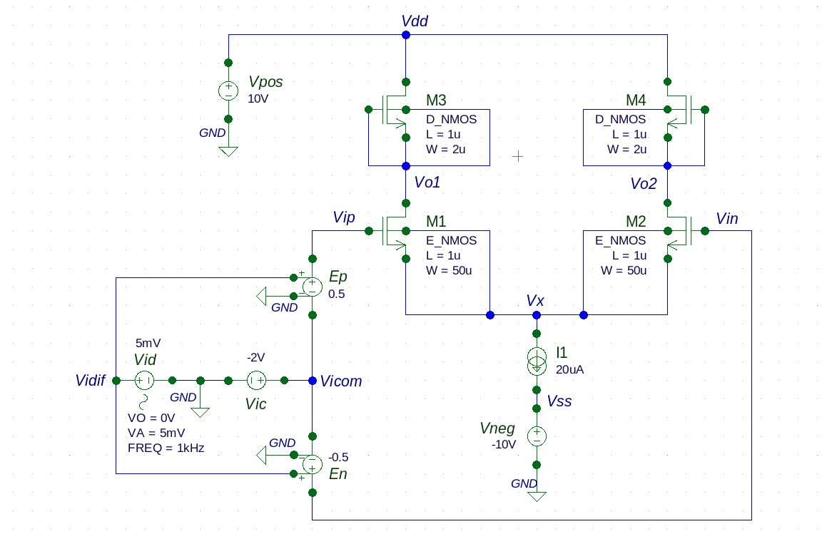
The differential input signal is generated from a sinusoidal source (Vid) feeding two voltage-controlled voltage sources (Ep and En). Sources Ep and En establish phase and reduce amplitude before modulating the common mode signal (Vic). This composite input signal drives the differential amplifer at Vip and Vin. The output is obtained at nodes Vo1 and Vo2.
Load the input deckinto SmartSpice, execute the simulation, and use SmartView to open the RAW file. The methods used to extract small signal gain are outlined below.
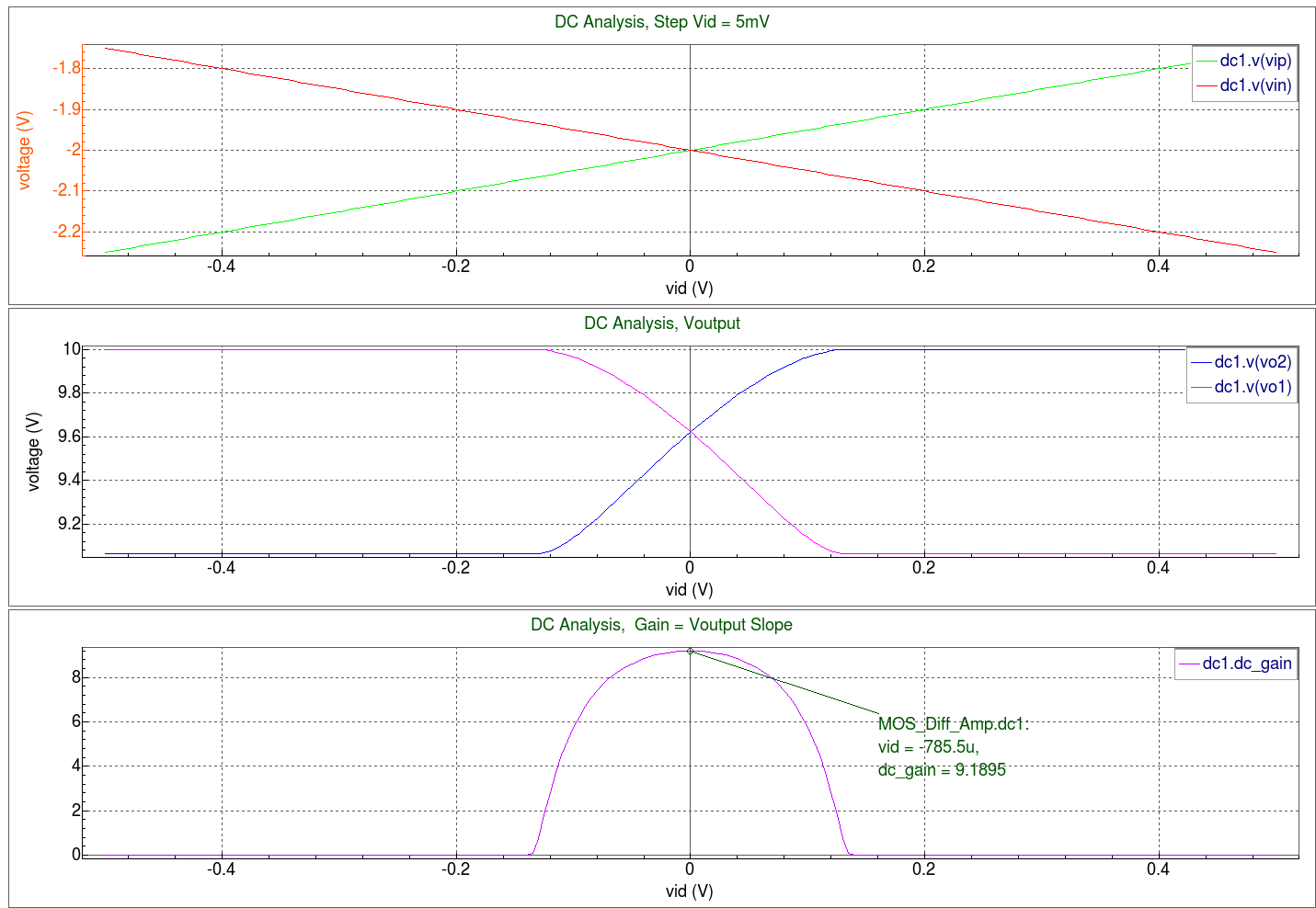
Small signal gain from a DC analysis is performed by calculating (.LET DC dc_gain) the ratio between the output's rate-of-change to the input's rate-of-change ("deriv" expression). The DC analysis' small signal gain is observed at the peak of the "dc_gain" curve.
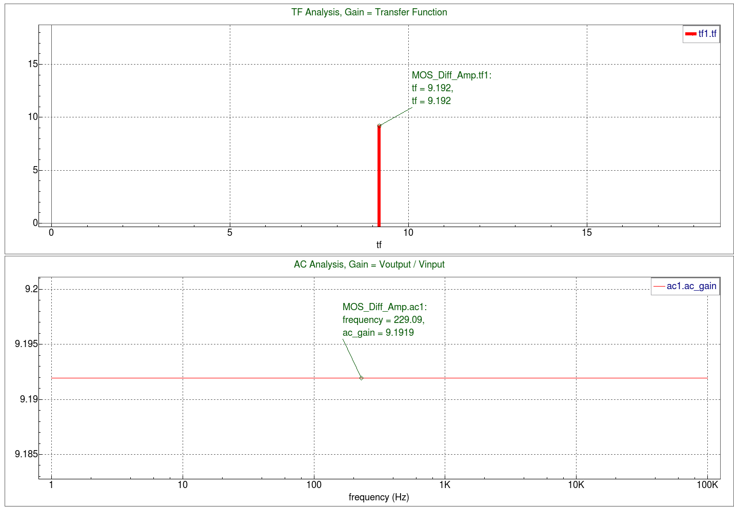
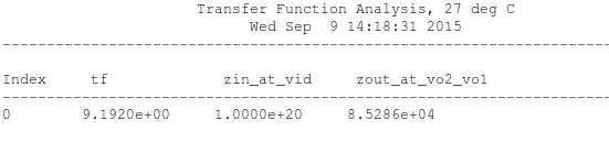
The Transfer Function (.TF) analysis reports small signal gain from an input to an output port, as well as the impedance observed at the two specified ports. The results can be observed in SmartSpice's output display window as Transfer Function Analysis results or with a single-point "tf" bar plot in SmartView.
A low-frequency sweep (.AC analysis) facilitates small signal gain calculations (.LET AC ac_gain) by computing the ratio of output to input signal amplitudes. As expected, the AC small signal gain is constant throughout the low-frequency sweep ("ac_gain" curve).
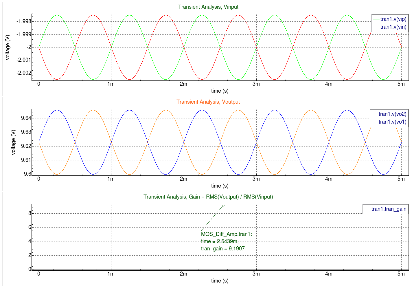
Performing a transient analysis over multiple cycles of a constant-amplitude, low frequency sinusoid (.AC analysis) facilitates small signal gain calculations by computing the ratio of output to input RMS values (.LET TRANS tran_gain). Although this approach's result can exhibit deviations from the previous methods, applying very small input amplitudes facilitates Transient Analysis gain calculations which correlate very closely to the previous methods ("tran_gain" curve).
Notice that increasing the input signal's amplitude will eventually create distortion in the output signal (caused by the Vo1 and Vo2 operating voltage's proximity to Vdd). As such, the calculated Transient Analysis gain will decrease as the input signal's amplitude increases. Thus, larger deviation in results will occur when compared to the previous methods. In summary, it is important to understand the relationship between the circuit's DC operating point and the effects it has on small signal gain calculations when using the Transient Analysis approach.
MOS_Diff_Amp.in
											* Schematic name: MOS_Diff_Amp

* Gateway 3.4.1.R Spice Netlist Generator
* Simulation timestamp: 09-Sep-2015 14:18:26
* Workspace name:       MOS_Diff_Amp.workspace
* Simulation name:      MOS_Diff_Amp.schlr

Vid Vidif GND SIN(0V 5mV 1kHz ) AC 5mV
En Vin Vicom Vidif GND -0.5
Vic Vicom GND DC "-2V"
Ep Vip Vicom Vidif GND 0.5
Vneg Vss GND DC "-10V"
I1 Vx Vss DC 20uA
Vpos Vdd GND DC 10V
M4 Vdd Vo2 Vo2 Vo2 D_NMOS L=1u W=2u
M3 Vdd Vo1 Vo1 Vo1 D_NMOS L=1u W=2u
M2 Vo2 Vin Vx Vx E_NMOS L=1u W=50u
M1 Vo1 Vip Vx Vx E_NMOS L=1u W=50u

* Global Nodes Declarations
.GLOBAL GND

* End of the netlist

*** DC Operating Point
.OP all

*** DC Analysis & Gain Calculation
.DC Vid -0.5 +0.5 0.005
.LET DC dc_gain = abs(deriv(Vo2-Vo1))

*** Transfer Function Analysis
.TF V(Vo2,Vo1) Vid

*** AC Analysis & Gain Calculation
.AC DEC 50 1 100K
.LET AC ac_gain = abs((Vo2-Vo1)/(Vip-Vin))

*** Transient Analysis & Gain Calculation
.TRAN 1us 5ms 0s 1us
.LET TRAN tran_gain = abs(rms(Vo2-Vo1)/rms(Vip-Vin))

*** Output, Options, and Control
.PRINT OP ALL
.PRINT TF ALL
.OPTIONS nomod nodeck post accurate

*** Model Cards
.model D_NMOS nmos (
+ level=3 kp=7.5e-6 gamma=0.5 phi=0.3 vt0=-2.0 lambda=0.025 )
.model E_NMOS nmos (
+ level=3 kp=7.5e-6 gamma=0.5 phi=0.3 vt0=+1.0 lambda=0.025 )

.END
021_dc_ac_tf_tran
[an error occurred while processing this directive]