16 : Using Different Methods of Parasitic Capacitance Extraction for Selected Regions (Mix & Match)
Minimum Required Versions: Expert 5.2204.3.R, Hipex 3.8.7.R
This example demonstrates running Hipex Parasitic Capacitance Extraction using VictoryRCx and Stellar Field Solvers for different areas of the same layout, and combining the results into common netlist. This technique is nicknamed "Mix & Match Extraction". It provides opportunity to select (non-overlapping) rectangular blocks on layout, and assign different extraction solvers to process different blocks and the rest of layout. Currently, Hipex supports 3 different solvers:
- Rule-based (heuristical imitation of field solving)
- VictoryRCx (Finite Element Method)
- Stellar (Boundary Element Method).
The functionality is available for Linux only.
1: Start Expert, load GDS layout
Run Expert Layout Editor.
Choose File->Import... . In appeared "Import Project" dialog:
- select GDS II in "File type" control;
- choose mm_exmp.gds file using dialog's file browser;
- choose technology file mm_exmp.tcn using "Technology" control;
- click "Open" button;
- choose cell array_of_pixel2_3x3 to open for extraction.
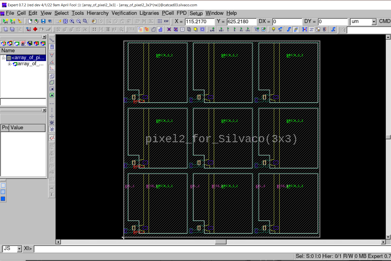
The sketch of layout (3x3 matrix of TFT cell) is shown on Figure1
2: Load Extraction Settings.
Load settings from mm_exmp.lpe file by choosing Verification->Extraction->Setup... and pressing Load button located at the bottom of appeared dialog.
3: Setting Mix&Match Blocks and Extraction Modes.
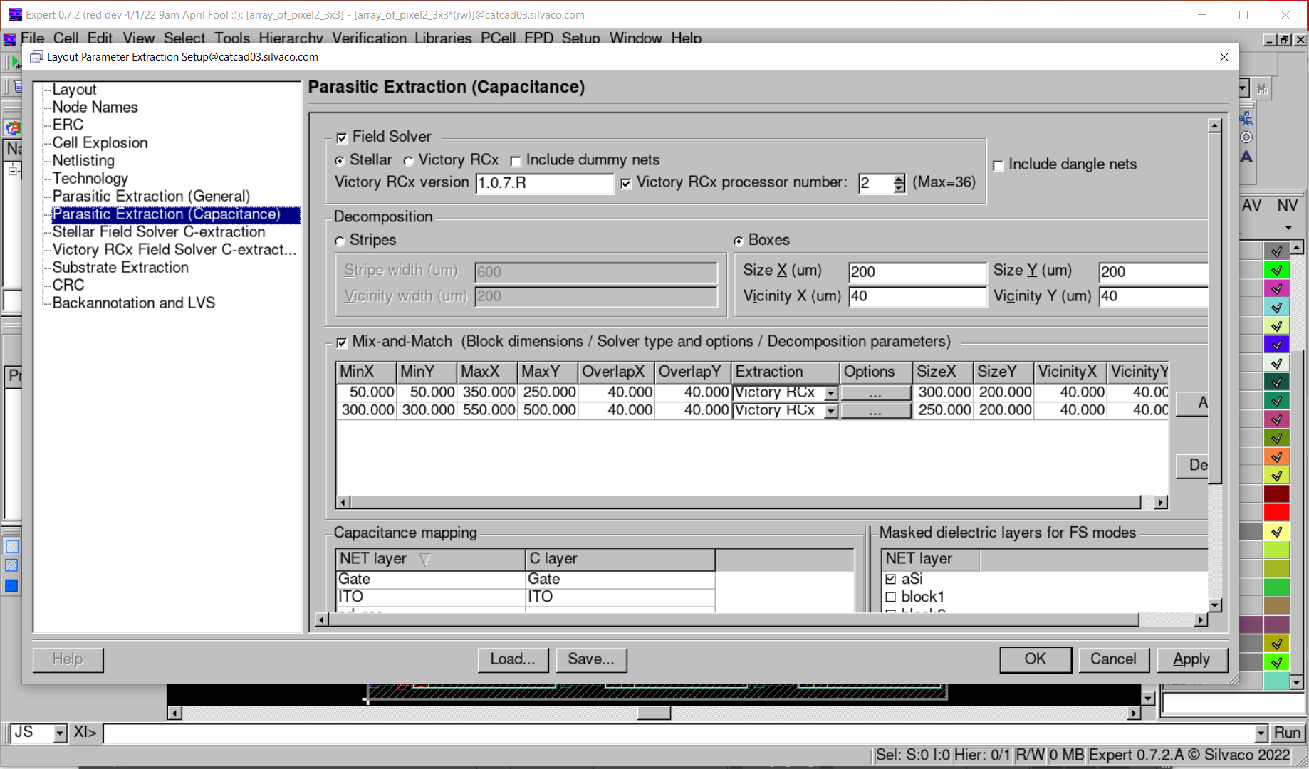
To provide usage of Stellar solver for the rest of layout (not covered by Mix&Match blocks), make sure Stellar radio button is ON in Field Solver group of Parasitic Extraction (Capacitance) tab from Layout Parameter Setup dialog, as shown on Figure2 ,and Boxes radio button is ON in Decomposition group with the values specified: SizeX=200, VicinityX=40, SizeY=200, VicinityY=40 (this provides splitting external part of layout into 9 boxes to accelerate Stellar performance).
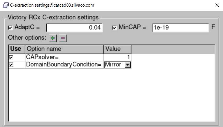
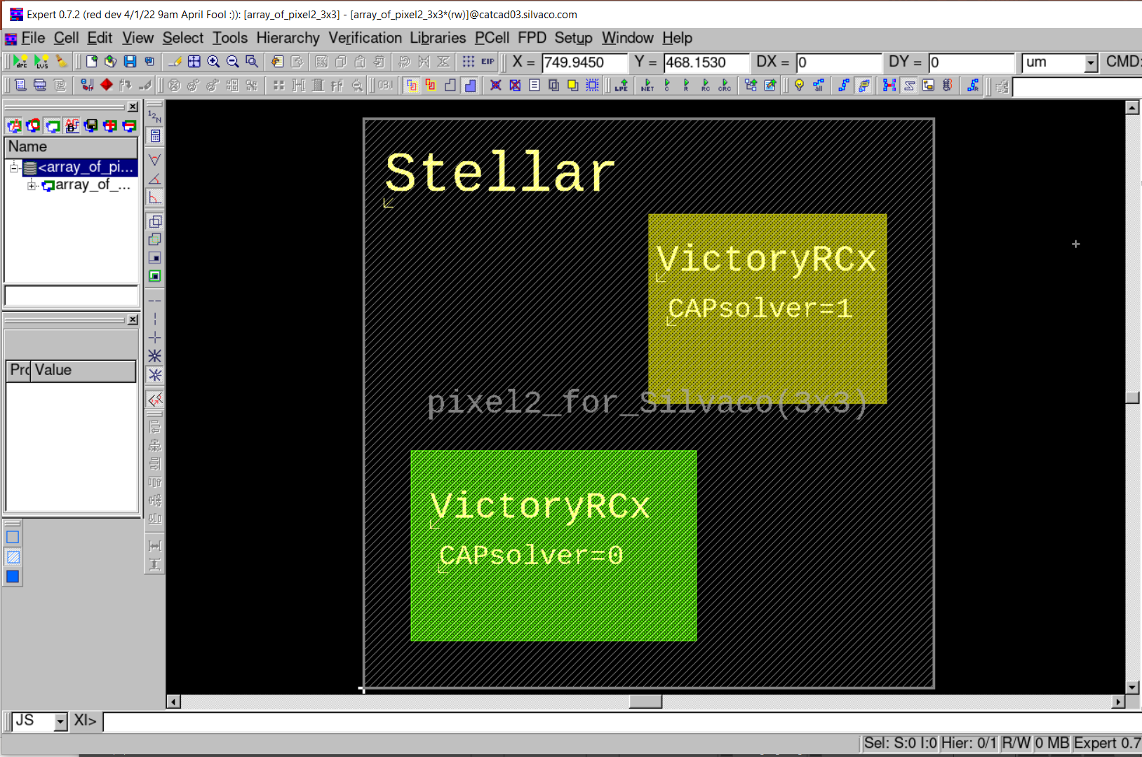
Inspect Mix-and-Match group. Verify that it is activated (checked) with 2 blocks specified, and using parameters as depicted on Figure2. Both blocks are set to use VictoryRCx simulator, but for second block the non-default option CAPsolver=1 is chosen (boosting performance, though with occasional convergence problems). To assure this assignment (CAPsolver=1), press at "Options" field in second row, and observe "VictoryRCx C-extraction settings" group in appeared dialog (see Figure3 ). The chosen Mix&Match blocks are shown on Figure4 .
Also, verify capacitance mapping (layers Gate, ITO, SD, via, M4 to be mapped ) and mapping of masked dielectric layers (layers Passivation, Via, OxideGate, NIP, aSi, IMDx to be selected) to ensure proper mask usage in process description.
3: Choosing Versions of Utilized Programs.
For variety of extraction settings, Hipex can call executables of VictoryRCx,DeckBuild,VictoryProcess,VictoryMesh to provide simulations and structure build. There is (optional) possibility to choose particular versions of abovementioned programs (otherwise, default versions of installed software to be called). VictoryRCx version can be assigned using appropriate field in Field Solver group of Parasitic Extraction (Capacitance) tab from Layout Parameter Setup dialog (see Figure2). Minimal VictoryRCx version to support integration with Hipex is 1.0.7.R .
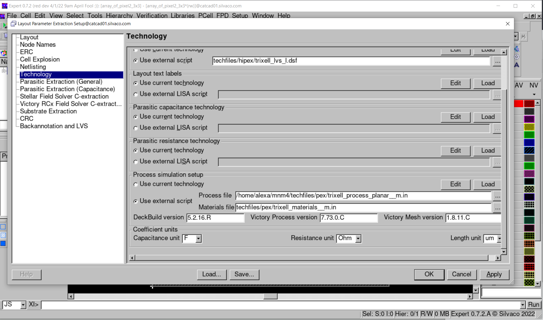
To assign versions of other programs: Open Technology tab of LPE Setup. Make sure minimal compatible (with Hipex) versions of DeckBuild(5.2.12.R), VictoryProcess(7.55.1.C),VictoryMesh (1.7.4.C) or newer ones are specified in Process simulation setup section (see Figure5 ).
4: Performing extraction.
Run netlist extraction Verification->Extraction->Hipex Net->Run Run capacitance extraction Verification->Extraction->Hipex C->Run Press Open Netlist button to view capacitance netlist.
mm_exmp.tcn
											TechnologyID = "Tft, ver. 0.0"
Version = 201
Unit = "um"
UnitValue = 1
Shapes
  {
  AllowOffGridWire = FALSE
  AllowOffGridEllipse = FALSE
  ApproximationType = POINTS
  ApproximationValue = 20
  AlignedY = FALSE
  Circumscribed = FALSE
  }
PurposeTable
  {
  Purpose
    {
    Number = 255
    PurposeType = drawing
    Name = "all"
    Alias = "all"
    }
  Purpose
    {
    Number = 254
    PurposeType = drawing
    Name = "cell"
    Alias = "cell"
    }
  Purpose
    {
    Number = 251
    PurposeType = drawing
    Name = "pin"
    Alias = "pin"
    }
  Purpose
    {
    Number = 250
    PurposeType = drawing
    Name = "boundary"
    Alias = "bnd"
    }
  Purpose
    {
    Number = 249
    PurposeType = drawing
    Name = "drawing9"
    Alias = "drw9"
    }
  Purpose
    {
    Number = 248
    PurposeType = drawing
    Name = "drawing8"
    Alias = "drw8"
    }
  Purpose
    {
    Number = 245
    PurposeType = drawing
    Name = "drawing5"
    Alias = "drw5"
    }
  Purpose
    {
    Number = 243
    PurposeType = drawing
    Name = "drawing3"
    Alias = "drw3"
    }
  Purpose
    {
    Number = 241
    PurposeType = drawing
    Name = "drawing1"
    Alias = "drw1"
    }
  Purpose
    {
    Number = 240
    PurposeType = drawing
    Name = "annotate"
    Alias = "ann"
    }
  Purpose
    {
    Number = 239
    PurposeType = drawing
    Name = "error"
    Alias = "err"
    }
  Purpose
    {
    Number = 236
    PurposeType = drawing
    Name = "tool0"
    Alias = "tl0"
    }
  Purpose
    {
    Number = 242
    PurposeType = drawing
    Name = "drawing2"
    Alias = "drw2"
    }
  Purpose
    {
    Number = 238
    PurposeType = drawing
    Name = "flight"
    Alias = "flt"
    }
  Purpose
    {
    Number = 235
    PurposeType = drawing
    Name = "tool1"
    Alias = "tl1"
    }
  Purpose
    {
    Number = 234
    PurposeType = drawing
    Name = "warning"
    Alias = "wan"
    }
  Purpose
    {
    Number = 247
    PurposeType = drawing
    Name = "drawing7"
    Alias = "drw7"
    }
  Purpose
    {
    Number = -12
    PurposeType = oaCustomFill
    Name = "oaCustomFill"
    Alias = "oal"
    }
  Purpose
    {
    Number = -11
    PurposeType = oaFillOPC
    Name = "oaFillOPC"
    Alias = "oaC"
    }
  Purpose
    {
    Number = -9
    PurposeType = oaAny
    Name = "oaAny"
    Alias = "any"
    }
  Purpose
    {
    Number = -8
    PurposeType = redundant
    Name = "redundant"
    Alias = "redt"
    }
  Purpose
    {
    Number = 244
    PurposeType = drawing
    Name = "drawing4"
    Alias = "drw4"
    }
  Purpose
    {
    Number = -10
    PurposeType = oaNo
    Name = "oaNo"
    Alias = "no"
    }
  Purpose
    {
    Number = -7
    PurposeType = gapFill
    Name = "gapFill"
    Alias = "gap"
    }
  Purpose
    {
    Number = -6
    PurposeType = annotation
    Name = "annotation"
    Alias = "anno"
    }
  Purpose
    {
    Number = -5
    PurposeType = OPCAntiSerif
    Name = "OPCAntiSerif"
    Alias = "OPSf"
    }
  Purpose
    {
    Number = -4
    PurposeType = OPCSerif
    Name = "OPCSerif"
    Alias = "OPC"
    }
  Purpose
    {
    Number = 253
    PurposeType = drawing
    Name = "net"
    Alias = "net"
    }
  Purpose
    {
    Number = 246
    PurposeType = drawing
    Name = "drawing6"
    Alias = "drw6"
    }
  Purpose
    {
    Number = 237
    PurposeType = drawing
    Name = "label"
    Alias = "lbl"
    }
  Purpose
    {
    Number = -3
    PurposeType = slot
    Name = "slot"
    Alias = "slt"
    }
  Purpose
    {
    Number = -2
    PurposeType = fill
    Name = "fill"
    Alias = "fil"
    }
  Purpose
    {
    Number = -1
    PurposeType = drawing
    Name = "drawing"
    Alias = "drg"
    }
  }
Layer
  {
  Name = "Gate"
  Wire
    {
    MiterAngle = 20
    Width = 0
    Joint = MITER
    End = BUTT
    }
  Stipple = "z89"
  Bitmap = "0000000008000000080000000200000001000100990033006600CC00990033006600CC00"
  Color = (255,0,0)
  GDS2Num = 1
  GDS2DataType = 0
  OA
    {
    LayerNumber = 1
    PurposeNumber = -1
    PurposeAbbreviation = "drawing"
    PurposeType = drawing
    Visible = TRUE
    Selectable = TRUE
    Valid = TRUE
    Priority = 1
    }
  Scope = FLAT
  UseGridParams = FALSE
  ScratchLayer = FALSE
  EdgeLayer = FALSE
  LineStyle = 0
  }
Layer
  {
  Name = "OxydeGate"
  Wire
    {
    MiterAngle = 20
    Width = 5
    Joint = MITER
    End = BUTT
    }
  Stipple = "51"
  Bitmap = "000000000800000008000000020000000100010088004400220011008800440022001100"
  Color = (164,164,164)
  GDS2Num = 71
  GDS2DataType = 0
  OA
    {
    LayerNumber = 71
    PurposeNumber = -1
    PurposeAbbreviation = "drawing"
    PurposeType = drawing
    Visible = TRUE
    Selectable = TRUE
    Valid = TRUE
    Priority = 2
    }
  Scope = FLAT
  UseGridParams = FALSE
  ScratchLayer = FALSE
  EdgeLayer = FALSE
  LineStyle = 0
  }
Layer
  {
  Name = "aSi"
  Wire
    {
    MiterAngle = 20
    Width = 4
    Joint = MITER
    End = BUTT
    }
  Stipple = "51"
  Bitmap = "000000000800000008000000020000000100010088004400220011008800440022001100"
  Color = (255,0,255)
  ColorName = "magenta"
  GDS2Num = 74
  GDS2DataType = 0
  OA
    {
    LayerNumber = 74
    PurposeNumber = -1
    PurposeAbbreviation = "drawing"
    PurposeType = drawing
    Visible = TRUE
    Selectable = TRUE
    Valid = TRUE
    Priority = 3
    }
  Scope = FLAT
  UseGridParams = FALSE
  ScratchLayer = FALSE
  EdgeLayer = FALSE
  LineStyle = 0
  }
Layer
  {
  Name = "SD"
  Wire
    {
    MiterAngle = 20
    Width = 10
    Joint = MITER
    End = BUTT
    }
  Stipple = "z29"
  Bitmap = "00000000080000000800000002000000010001005500AA005500AA005500AA005500AA00"
  Color = (0,255,0)
  ColorName = "green"
  GDS2Num = 11
  GDS2DataType = 0
  OA
    {
    LayerNumber = 11
    PurposeNumber = -1
    PurposeAbbreviation = "drawing"
    PurposeType = drawing
    Visible = TRUE
    Selectable = TRUE
    Valid = TRUE
    Priority = 5
    }
  Scope = FLAT
  UseGridParams = FALSE
  ScratchLayer = FALSE
  EdgeLayer = FALSE
  LineStyle = 0
  }
Layer
  {
  Name = "NIP"
  Wire
    {
    MiterAngle = 20
    Width = 5
    Joint = MITER
    End = BUTT
    }
  Stipple = "StippleDef"
  Bitmap = "00000000080000000800000002000000010001005500AA005500AA005500AA005500AA00"
  Color = (0,0,255)
  ColorName = "blue"
  GDS2Num = 8
  GDS2DataType = 0
  OA
    {
    LayerNumber = 8
    PurposeNumber = -1
    PurposeAbbreviation = "drawing"
    PurposeType = drawing
    Visible = TRUE
    Selectable = TRUE
    Valid = TRUE
    Priority = 6
    }
  Scope = FLAT
  UseGridParams = FALSE
  ScratchLayer = FALSE
  EdgeLayer = FALSE
  LineStyle = 0
  }
Layer
  {
  Name = "ITO"
  Wire
    {
    MiterAngle = 20
    Width = 5
    Joint = MITER
    End = BUTT
    }
  Stipple = "STP_H_BDIAG"
  Color = (10,98,245)
  GDS2Num = 72
  GDS2DataType = 0
  OA
    {
    LayerNumber = 72
    PurposeNumber = -1
    PurposeAbbreviation = "drawing"
    PurposeType = drawing
    Visible = TRUE
    Selectable = TRUE
    Valid = TRUE
    Priority = 7
    }
  Scope = FLAT
  UseGridParams = FALSE
  ScratchLayer = FALSE
  EdgeLayer = FALSE
  LineStyle = 0
  }
Layer
  {
  Name = "IMDx"
  Wire
    {
    MiterAngle = 20
    Width = 10
    Joint = MITER
    End = BUTT
    }
  Stipple = "StippleDef"
  Bitmap = "00000000080000000800000002000000010001005500AA005500AA005500AA005500AA00"
  Color = (127,127,127)
  ColorName = "gray dark"
  GDS2Num = 70
  GDS2DataType = 0
  OA
    {
    LayerNumber = 70
    PurposeNumber = -1
    PurposeAbbreviation = "drawing"
    PurposeType = drawing
    Visible = TRUE
    Selectable = TRUE
    Valid = TRUE
    Priority = 8
    }
  Scope = FLAT
  UseGridParams = FALSE
  ScratchLayer = FALSE
  EdgeLayer = FALSE
  LineStyle = 0
  }
Layer
  {
  Name = "Via"
  Wire
    {
    MiterAngle = 20
    Width = 10
    Joint = MITER
    End = BUTT
    }
  Stipple = "z29"
  Bitmap = "00000000080000000800000002000000010001005500AA005500AA005500AA005500AA00"
  Color = (0,255,0)
  ColorName = "green"
  GDS2Num = 4
  GDS2DataType = 0
  OA
    {
    LayerNumber = 4
    PurposeNumber = -1
    PurposeAbbreviation = "drawing"
    PurposeType = drawing
    Visible = TRUE
    Selectable = TRUE
    Valid = TRUE
    Priority = 9
    }
  Scope = FLAT
  UseGridParams = FALSE
  ScratchLayer = FALSE
  EdgeLayer = FALSE
  LineStyle = 0
  }
Layer
  {
  Name = "M4"
  Wire
    {
    MiterAngle = 20
    Width = 0
    Joint = MITER
    End = BUTT
    }
  Stipple = "z89"
  Bitmap = "0000000008000000080000000200000001000100990033006600CC00990033006600CC00"
  Color = (202,53,176)
  GDS2Num = 5
  GDS2DataType = 0
  OA
    {
    LayerNumber = 5
    PurposeNumber = -1
    PurposeAbbreviation = "drawing"
    PurposeType = drawing
    Visible = TRUE
    Selectable = TRUE
    Valid = TRUE
    Priority = 10
    }
  Scope = FLAT
  UseGridParams = FALSE
  ScratchLayer = FALSE
  EdgeLayer = FALSE
  LineStyle = 0
  }
Layer
  {
  Name = "Passivation"
  Wire
    {
    MiterAngle = 20
    Width = 0
    Joint = MITER
    End = BUTT
    }
  Stipple = "empty"
  Bitmap = "000000000800000008000000020000000100010000000000000000000000000000000000"
  Color = (128,215,215)
  ColorName = "0"
  GDS2Num = 80
  GDS2DataType = 0
  OA
    {
    LayerNumber = 80
    PurposeNumber = -1
    PurposeAbbreviation = "drawing"
    PurposeType = drawing
    Visible = TRUE
    Selectable = TRUE
    Valid = TRUE
    Priority = 11
    }
  Scope = FLAT
  UseGridParams = FALSE
  ScratchLayer = FALSE
  EdgeLayer = FALSE
  LineStyle = 0
  }
Layer
  {
  Name = "tft_rec"
  Wire
    {
    MiterAngle = 20
    Width = 0
    Joint = MITER
    End = BUTT
    }
  Stipple = "STP_H_DIAGCROSS"
  Color = (218,246,158)
  ColorName = "0"
  GDS2Num = 0
  GDS2DataType = 0
  OA
    {
    LayerNumber = -1
    PurposeNumber = -1
    PurposeAbbreviation = "drawing"
    PurposeType = drawing
    Visible = TRUE
    Selectable = TRUE
    Valid = TRUE
    Priority = 12
    }
  Scope = FLAT
  UseGridParams = FALSE
  ScratchLayer = TRUE
  EdgeLayer = FALSE
  LineStyle = 0
  }
Layer
  {
  Name = "via"
  Wire
    {
    MiterAngle = 20
    Width = 0
    Joint = MITER
    End = BUTT
    }
  Stipple = "STP_H_DENSE7"
  Color = (74,6,238)
  ColorName = "0"
  GDS2Num = 81
  GDS2DataType = 0
  OA
    {
    LayerNumber = -1
    PurposeNumber = -1
    PurposeAbbreviation = "drawing"
    PurposeType = drawing
    Visible = TRUE
    Selectable = TRUE
    Valid = TRUE
    Priority = 13
    }
  Scope = FLAT
  UseGridParams = FALSE
  ScratchLayer = TRUE
  EdgeLayer = FALSE
  LineStyle = 0
  }
Layer
  {
  Name = "pd_rec"
  Wire
    {
    MiterAngle = 20
    Width = 0
    Joint = MITER
    End = BUTT
    }
  Stipple = "STP_H_CROSS"
  Color = (227,245,225)
  ColorName = "0"
  GDS2Num = 82
  GDS2DataType = 0
  OA
    {
    LayerNumber = -1
    PurposeNumber = -1
    PurposeAbbreviation = "drawing"
    PurposeType = drawing
    Visible = TRUE
    Selectable = TRUE
    Valid = TRUE
    Priority = 14
    }
  Scope = FLAT
  UseGridParams = FALSE
  ScratchLayer = TRUE
  EdgeLayer = FALSE
  LineStyle = 0
  }
Layer
  {
  Name = "sd_pd"
  Wire
    {
    MiterAngle = 20
    Width = 0
    Joint = MITER
    End = BUTT
    }
  Stipple = "STP_H_DENSE7"
  Color = (21,83,71)
  ColorName = "0"
  GDS2Num = 83
  GDS2DataType = 0
  OA
    {
    LayerNumber = -1
    PurposeNumber = -1
    PurposeAbbreviation = "drawing"
    PurposeType = drawing
    Visible = TRUE
    Selectable = TRUE
    Valid = TRUE
    Priority = 15
    }
  Scope = FLAT
  UseGridParams = FALSE
  ScratchLayer = TRUE
  EdgeLayer = FALSE
  LineStyle = 0
  }
Layer
  {
  Name = "sd_connect"
  Wire
    {
    MiterAngle = 20
    Width = 0
    Joint = MITER
    End = BUTT
    }
  Stipple = "STP_H_DENSE5"
  Color = (20,140,92)
  ColorName = "0"
  GDS2Num = 84
  GDS2DataType = 0
  OA
    {
    LayerNumber = -1
    PurposeNumber = -1
    PurposeAbbreviation = "drawing"
    PurposeType = drawing
    Visible = TRUE
    Selectable = TRUE
    Valid = TRUE
    Priority = 16
    }
  Scope = FLAT
  UseGridParams = FALSE
  ScratchLayer = TRUE
  EdgeLayer = FALSE
  LineStyle = 0
  }
Layer
  {
  Name = "channel"
  Wire
    {
    MiterAngle = 20
    Width = 0
    Joint = MITER
    End = BUTT
    }
  Stipple = "STP_H_DENSE6"
  Color = (183,65,125)
  ColorName = "0"
  GDS2Num = 85
  GDS2DataType = 0
  OA
    {
    LayerNumber = -1
    PurposeNumber = -1
    PurposeAbbreviation = "drawing"
    PurposeType = drawing
    Visible = TRUE
    Selectable = TRUE
    Valid = TRUE
    Priority = 17
    }
  Scope = FLAT
  UseGridParams = FALSE
  ScratchLayer = TRUE
  EdgeLayer = FALSE
  LineStyle = 0
  }
Layer
  {
  Name = "sd_ovl"
  Wire
    {
    MiterAngle = 20
    Width = 0
    Joint = MITER
    End = BUTT
    }
  Stipple = "STP_H_CROSS"
  Color = (103,145,13)
  ColorName = "0"
  GDS2Num = 86
  GDS2DataType = 0
  OA
    {
    LayerNumber = -1
    PurposeNumber = -1
    PurposeAbbreviation = "drawing"
    PurposeType = drawing
    Visible = TRUE
    Selectable = TRUE
    Valid = TRUE
    Priority = 18
    }
  Scope = FLAT
  UseGridParams = FALSE
  ScratchLayer = TRUE
  EdgeLayer = FALSE
  LineStyle = 0
  }
Layer
  {
  Name = "sd_aux"
  Wire
    {
    MiterAngle = 20
    Width = 0
    Joint = MITER
    End = BUTT
    }
  Stipple = "STP_H_CROSS"
  Color = (247,129,61)
  ColorName = "0"
  GDS2Num = 87
  GDS2DataType = 0
  OA
    {
    LayerNumber = -1
    PurposeNumber = -1
    PurposeAbbreviation = "drawing"
    PurposeType = drawing
    Visible = TRUE
    Selectable = TRUE
    Valid = TRUE
    Priority = 19
    }
  Scope = FLAT
  UseGridParams = FALSE
  ScratchLayer = TRUE
  EdgeLayer = FALSE
  LineStyle = 0
  }
Layer
  {
  Name = "ffzone"
  Wire
    {
    MiterAngle = 20
    Width = 0
    Joint = MITER
    End = BUTT
    }
  Stipple = "STP_H_DENSE5"
  Color = (216,232,72)
  ColorName = "0"
  GDS2Num = 88
  GDS2DataType = 0
  OA
    {
    LayerNumber = -1
    PurposeNumber = -1
    PurposeAbbreviation = "drawing"
    PurposeType = drawing
    Visible = TRUE
    Selectable = TRUE
    Valid = TRUE
    Priority = 20
    }
  Scope = FLAT
  UseGridParams = FALSE
  ScratchLayer = TRUE
  EdgeLayer = FALSE
  LineStyle = 0
  }
Layer
  {
  Name = "SUB"
  Wire
    {
    MiterAngle = 20
    Width = 0
    Joint = MITER
    End = BUTT
    }
  Stipple = "STP_H_DIAGCROSS"
  Color = (128,0,0)
  ColorName = "0"
  GDS2Num = -1
  GDS2DataType = 0
  OA
    {
    LayerNumber = -1
    PurposeNumber = -1
    PurposeAbbreviation = "drawing"
    PurposeType = drawing
    Visible = TRUE
    Selectable = TRUE
    Valid = TRUE
    Priority = 21
    }
  Scope = FLAT
  UseGridParams = FALSE
  ScratchLayer = TRUE
  EdgeLayer = FALSE
  LineStyle = 0
  }
Layer
  {
  Name = "Dev_Labels"
  Wire
    {
    MiterAngle = 20
    Width = 0
    Joint = MITER
    End = BUTT
    }
  Stipple = "STP_H_CROSS"
  Color = (255,0,0)
  ColorName = "0"
  GDS2Num = -1
  GDS2DataType = 0
  OA
    {
    LayerNumber = -1
    PurposeNumber = -1
    PurposeAbbreviation = "drawing"
    PurposeType = drawing
    Visible = TRUE
    Selectable = TRUE
    Valid = TRUE
    Priority = 22
    }
  Scope = FLAT
  UseGridParams = FALSE
  ScratchLayer = TRUE
  EdgeLayer = FALSE
  LineStyle = 0
  }
Layer
  {
  Name = "Lay2"
  Wire
    {
    MiterAngle = 20
    Width = 0
    Joint = EXTEND
    End = EXTEND
    }
  Stipple = "STP_H_CROSS"
  Color = (255,255,127)
  ColorName = "0"
  GDS2Num = 2
  GDS2DataType = 0
  OA
    {
    LayerNumber = 2
    PurposeNumber = -1
    PurposeAbbreviation = "drawing"
    PurposeType = drawing
    Visible = TRUE
    Selectable = TRUE
    Valid = TRUE
    Priority = 23
    }
  Scope = FLAT
  UseGridParams = FALSE
  ScratchLayer = FALSE
  EdgeLayer = FALSE
  LineStyle = 0
  }
Layer
  {
  Name = "Via_holes"
  Wire
    {
    MiterAngle = 20
    Width = 0
    Joint = EXTEND
    End = EXTEND
    }
  Stipple = "STP_H_DIAGCROSS"
  Color = (180,236,60)
  ColorName = "0"
  GDS2Num = -32768
  GDS2DataType = -32768
  OA
    {
    LayerNumber = -32768
    PurposeNumber = -1
    PurposeAbbreviation = "drawing"
    PurposeType = drawing
    Visible = TRUE
    Selectable = TRUE
    Valid = TRUE
    Priority = 24
    }
  Scope = FLAT
  UseGridParams = FALSE
  ScratchLayer = TRUE
  EdgeLayer = FALSE
  LineStyle = 0
  }
Layer
  {
  Name = "sd_aux_tmp"
  Wire
    {
    MiterAngle = 20
    Width = 0
    Joint = EXTEND
    End = EXTEND
    }
  Stipple = "STP_H_DENSE6"
  Color = (163,181,33)
  ColorName = "0"
  GDS2Num = -32768
  GDS2DataType = -32768
  OA
    {
    LayerNumber = -32768
    PurposeNumber = -1
    PurposeAbbreviation = "drawing"
    PurposeType = drawing
    Visible = TRUE
    Selectable = TRUE
    Valid = TRUE
    Priority = 25
    }
  Scope = FLAT
  UseGridParams = FALSE
  ScratchLayer = TRUE
  EdgeLayer = FALSE
  LineStyle = 0
  }
Layer
  {
  Name = "ito"
  Wire
    {
    MiterAngle = 20
    Width = 0
    Joint = EXTEND
    End = EXTEND
    }
  Stipple = "STP_H_DIAGCROSS"
  Color = (46,194,58)
  ColorName = "0"
  GDS2Num = -32768
  GDS2DataType = -32768
  OA
    {
    LayerNumber = -32768
    PurposeNumber = -1
    PurposeAbbreviation = "drawing"
    PurposeType = drawing
    Visible = TRUE
    Selectable = TRUE
    Valid = TRUE
    Priority = 26
    }
  Scope = FLAT
  UseGridParams = FALSE
  ScratchLayer = TRUE
  EdgeLayer = FALSE
  LineStyle = 0
  }
Layer
  {
  Name = "m4"
  Wire
    {
    MiterAngle = 20
    Width = 0
    Joint = EXTEND
    End = EXTEND
    }
  Stipple = "STP_H_CROSS"
  Color = (155,125,73)
  ColorName = "0"
  GDS2Num = -32768
  GDS2DataType = -32768
  OA
    {
    LayerNumber = -32768
    PurposeNumber = -1
    PurposeAbbreviation = "drawing"
    PurposeType = drawing
    Visible = TRUE
    Selectable = TRUE
    Valid = TRUE
    Priority = 27
    }
  Scope = FLAT
  UseGridParams = FALSE
  ScratchLayer = TRUE
  EdgeLayer = FALSE
  LineStyle = 0
  }
Layer
  {
  Name = "gate"
  Wire
    {
    MiterAngle = 20
    Width = 0
    Joint = EXTEND
    End = EXTEND
    }
  Stipple = "STP_H_DENSE5"
  Color = (129,71,107)
  ColorName = "0"
  GDS2Num = -32768
  GDS2DataType = -32768
  OA
    {
    LayerNumber = -32768
    PurposeNumber = -1
    PurposeAbbreviation = "drawing"
    PurposeType = drawing
    Visible = TRUE
    Selectable = TRUE
    Valid = TRUE
    Priority = 28
    }
  Scope = FLAT
  UseGridParams = FALSE
  ScratchLayer = TRUE
  EdgeLayer = FALSE
  LineStyle = 0
  }
Layer
  {
  Name = "block2"
  Wire
    {
    MiterAngle = 20
    Width = 0
    Joint = EXTEND
    End = EXTEND
    }
  Stipple = "STP_H_DENSE2"
  Color = (170,170,0)
  ColorName = "0"
  GDS2Num = 91
  GDS2DataType = 0
  OA
    {
    LayerNumber = -1
    PurposeNumber = -1
    PurposeAbbreviation = "drawing"
    PurposeType = drawing
    Visible = TRUE
    Selectable = TRUE
    Valid = TRUE
    Priority = 29
    }
  Scope = FLAT
  UseGridParams = FALSE
  ScratchLayer = FALSE
  EdgeLayer = FALSE
  LineStyle = 0
  }
Layer
  {
  Name = "block1"
  Wire
    {
    MiterAngle = 20
    Width = 0
    Joint = EXTEND
    End = EXTEND
    }
  Stipple = "STP_H_DENSE3"
  Color = (85,255,0)
  ColorName = "0"
  GDS2Num = 90
  GDS2DataType = 0
  OA
    {
    LayerNumber = -1
    PurposeNumber = -1
    PurposeAbbreviation = "drawing"
    PurposeType = drawing
    Visible = TRUE
    Selectable = TRUE
    Valid = TRUE
    Priority = 30
    }
  Scope = FLAT
  UseGridParams = FALSE
  ScratchLayer = FALSE
  EdgeLayer = FALSE
  LineStyle = 0
  }
Device
  {
  Type = "generic"
  SpName = "TFT"
  Params = 0
  DevLay
    {
    NameL = "tft_rec"
    TypeL = REC
    }
  DevLay
    {
    NameL = "sd_connect"
    TypeL = PIN
    }
  DevLay
    {
    NameL = "Gate"
    TypeL = PIN
    }
  DevLay
    {
    NameL = "sd_connect"
    TypeL = PIN
    }
  GenericParam
    {
    Element = "NMOS"
    Type = "BY_SHAPE"
    Pins = "D,G,S"
    Aux = "sd_ovl,channel,sd_aux"
    Proc = "tft"
    File = "../techfiles/hipex/lvs_d.lisa"
    }
  }
Device
  {
  Type = "generic"
  SpName = "PD"
  Params = 0
  DevLay
    {
    NameL = "pd_rec"
    TypeL = REC
    }
  DevLay
    {
    NameL = "ITO"
    TypeL = PIN
    }
  DevLay
    {
    NameL = "sd_pd"
    TypeL = PIN
    }
  GenericParam
    {
    Element = "D"
    Type = "BY_SHAPE"
    Pins = "POS,NEG"
    Aux = "ffzone"
    Proc = "pd"
    File = "../techfiles/hipex/lvs_d.lisa"
    }
  }
Connect = ("M4","Gate","via")
Connect = ("sd_connect","M4","via")
Connect = ("sd_pd","sd_connect")
Connect = ("ITO","M4","via")
Connect = ("sd_connect","SD")
GridParams
  {
  MinGridStep = 1
  SnapCursorStepX = 1
  SnapCursorStepY = 1
  SnapDepend = 0
  SnapCursorRatioX = 0
  SnapCursorRatioY = 0
  GridColor = (0,0,0)
  GridType = 0
  AutomaticGridType = 0
  UserVisualGridStepX = 20
  UserVisualGridStepY = 20
  SuperGridStepX = 4
  SuperGridStepY = 4
  }
InstanceGridParams
  {
  MinGridStep = 100
  SnapCursorStepX = 1
  SnapCursorStepY = 1
  SnapDepend = 0
  SnapCursorRatioX = 0
  SnapCursorRatioY = 0
  GridColor = (0,0,0)
  GridType = 0
  AutomaticGridType = 0
  UserVisualGridStepX = 10
  UserVisualGridStepY = 10
  SuperGridStepX = 10
  SuperGridStepY = 10
  }
NetToCap = ("Gate","Gate")
NetToCap = ("SD","SD")
NetToCap = ("ITO","ITO")
NetToCap = ("M4","M4")
NetToCap = ("via","via")
MaskedDielectric = ("OxydeGate")
MaskedDielectric = ("aSi")
MaskedDielectric = ("IMDx")
MaskedDielectric = ("NIP")
MaskedDielectric = ("Via")
MaskedDielectric = ("Passivation")
Rule = ("Min Width = 4","Gate")
Rule = ("Min Space = 4","Gate")
Rule = ("Sheet Resistance = 0.26","Gate")
Rule = ("Min Width = 4","SD")
Rule = ("Min Space = 4","SD")
Rule = ("Min Width = 4","ITO")
Rule = ("Min Space = 4","ITO")
Rule = ("Min Width = 4","Via")
Rule = ("Min Space = 4","Via")
Rule = ("Min Width = 4","M4")
Rule = ("Min Space = 4","M4")
Rule = ("Sheet Resistance = 0.04","M4")
run_c.lisa
											INCLUDE ("mm_exmp_opt.lisa");
INCLUDE ("mm_exmp_net_cmd.lisa");

HIPEX_SUMMARY_PATH                      = "/home/alexa/webexaples/16";
HDB READ;
print("Writing Mix-and-Match Database  ...");
HDB WRITE_MIX_AND_MATCH /FULL  "default" 200 200 40 40 /MNMBLOCKS="mm_exmp_mnm_cmd.lisa";
print("Mix-and-Match OK.");
CPX MAIN "default" /rewrite /mnm;
netlist spice/hier/c "/home/alexa/webexaples/16/array_of_pixel2_3x3_c_hier_2blockCl_restStlr_200_200.spice";
mm_exmp_opt.lisa
											!--------------------------------------------------------------------
!Run file
!DESIGN    : design
!TECHNO    : techno
!USER      :
!TIME      : Thu Jun  9 21:46:57 2022

!--------------------------------------------------------------------
TOP_CELL                                = "array_of_pixel2_3x3";

HIPEX_DB_DIRECTORY                      = "database";
!--------------------------------------------------------------------
!Extraction: LISA template command file
!--------------------------------------------------------------------

!--------------------------------------------------------------------
!Layout parameters
!--------------------------------------------------------------------
HIPEX_LAYOUT_FORMAT                     = "GDS";
HIPEX_LAYOUT_FILE                       = "array_of_pixel2_3x3$HPX.gds";
HIPEX_OVERLAP_INSTANCE_CHECK            = "NO";
HIPEX_SUPPRESS_NOTEMPTY                 = "YES";
HIPEX_NON45_FLAG                        = "NO";

!--------------------------------------------------------------------
!Connectivity parameters
!--------------------------------------------------------------------
HIPEX_TERNARY_CONNECT_THROUGH_TOUCH     = "NO";

!--------------------------------------------------------------------
!Output parameters
!--------------------------------------------------------------------
HIPEX_COMMENT_MODEL                     = "YES";
HIPEX_COMMENT_TOP_SUBCKT                = "NO";
HIPEX_HIER_SPICE_WL_NAME                = "/home/alexa/webexaples/16/array_of_pixel2_3x3_hier.spice";
HIPEX_MOSFET_LW_ONLY                    = "NO";
HIPEX_MOSFET_EXCLUDE_W_SD               = "NO";
HIPEX_OUTPUT_SPICE_ATTRIBUTES           = "YES";
HIPEX_CAP_OUTPUT_LW                     = "NO";
HIPEX_RES_OUTPUT_LW                     = "YES";
HIPEX_CAP_OUTPUT_AREA_PERIMETER         = "YES";
HIPEX_OUTPUT_SPICE_FORMAT               = "HSPICE";
HIPEX_PININFO                           = "NO";
HIPEX_PRINT_MESSAGES                    = "NO";
NETLIST_OUTPUT_PM                       = "NO";
NETLIST_DISTRIBUTION_MODE               = "ACCURATELADDER";
NETLIST_LINE_LENGTH                     = 80;
NETLIST_EXCLUDE_LIBRARY_PREFIX          = "NO";
NETLIST_GLOBALS_IN_SUBCKT_PINS          = "YES";
NETLIST_TEXTED_PINS                     = "NO";
NETLIST_LIBRARIES                       = {};

!--------------------------------------------------------------------
!ERC parameters
!--------------------------------------------------------------------
HIPEX_DANGLE_FLAG                       = "YES";
HIPEX_CAP_MESSAGE                       = "NO";
HIPEX_DIODE_MESSAGE                     = "NO";
HIPEX_RENAME_OPENS                      = "YES";
HIPEX_MULTILABEL_NAME                   = "";
HIPEX_SOFTCHECK_WARNINGS_AS_ERRORS      = "NO";

!--------------------------------------------------------------------
!Node Name parameters
!--------------------------------------------------------------------
HIPEX_HIERARCHY_SEPARATOR               = "/";
HIPEX_NODE_NAME_SEPARATOR               = "_";
HIPEX_DEFAULT_INSTANCE_PREFIX           = "I";
HIPEX_DEFAULT_NODE_PREFIX               = "#";
HIPEX_DELETE_BAD_CHAR                   = "YES";
HIPEX_XY_LOCATION                       = "NO";
HIPEX_CASE_SENSITIVE_NET_NAMES          = "YES";
HIPEX_AUTOGENERATE_LOCAL                = "YES";
POWER_NODE                              = {};
GROUND_NODE                             = {"Subs"};
GLOBAL_TEXT_LIST                        = {"Subs"};
HIPEX_PIN_DELIMITER                     = ":";

!--------------------------------------------------------------------
!Explosion parameters
!--------------------------------------------------------------------
HIPEX_WIRING_EXPLODE                    = "NO";
HIPEX_KEEP_FLATTEN_CELLS                = "YES";
HIPEX_TEXT_TOP                          = "NO";
HIPEX_AUTO_EXPLODE                      = "NO";
HIPEX SET_CELL_OPTIONS {"pixel2_for_Silvaco"} /EXPLODE;
HIPEX SET_CELL_OPTIONS {"array_of_pixel2_3x3"} /EXPLODE;

!--------------------------------------------------------------------
!Pins parameters
!--------------------------------------------------------------------
HIPEX_IGNORE_DANGLE_PINS                = "YES";

!--------------------------------------------------------------------
!BackAnnotate parameters
!--------------------------------------------------------------------
HIPEX_BACKANNOTATE                      = "NO";

!--------------------------------------------------------------------
!Process Simulation and Materials parameters
!--------------------------------------------------------------------
HIPEX_PROCESS_FILE                      = "../techfiles/pex/process_planar__m.in";
HIPEX_MATERIALS_FILE                    = "../techfiles/pex/materials__m.in";
HIPEX_DECKBUILD_VERSION                 = "5.2.16.R";
HIPEX_VICTORY_PROCESS_VERSION           = "7.76.1.R";
HIPEX_VICTORY_MESH_VERSION              = "1.8.11.C";

!--------------------------------------------------------------------
!Capacitance Extraction parameters
!--------------------------------------------------------------------
CPX_COUPLED_THRESHOLD                   = 0.0;
CPX_EXTRACT_DANGLES                     = "NO";
CPX_OUTPUT_DUMMY_CAPA                   = "NO";
CPX_FIELD_SOLVER                        = "STELLAR";

!--------------------------------------------------------------------
!Stellar Field Solver C-extraction parameters
!--------------------------------------------------------------------
CPX_STEP_X                              = 0.5;
CPX_STEP_Y                              = 0.5;
CPX_STEP_Z                              = 0.5;
CPX_PRECISION                           = 0.1;
CPX_MAX_ITER                            = 100;
CPX_BOX                                 = "NO";
CPX_BOX_VALUES_XMIN                     = 0.0;
CPX_BOX_VALUES_XMAX                     = 0.0;
CPX_BOX_VALUES_YMIN                     = 0.0;
CPX_BOX_VALUES_YMAX                     = 0.0;
CPX_FILTER                              = "NO";
CPX_CAPA_MIN                            = 1e-19;
CPX_RENEW                               = "NO";
CPX_SAVE_FILE                           = "/home/alexa/webexaples/16/RenewSavedFile.sav";

!--------------------------------------------------------------------
!Victory RCx Capacitance Extraction parameters
!--------------------------------------------------------------------
CPX_VICTORYRCX_EXTRACTION_FILE          = "mm_exmp_victoryrcx_c_cmd.in";
CPX_VICTORYRCX_VERSION                  = "1.0.7.R";
CPX_VICTORYRCX_PARALLEL_MODE            = "YES";
CPX_VICTORYRCX_CPU_NUMBER               = 2;

!--------------------------------------------------------------------
!Resistance Extraction parameters
!--------------------------------------------------------------------
RPX_SERIAL_MERGE_THRESHOLD              = 0.0;
RPX_OUTPUT_XY                           = "YES";
RPX_OUTPUT_LAYER_NAMES                  = "YES";
RPX_SKIP_POWER                          = "YES";
RPX_USE_TEXTS_AS_SUBNODES               = "NO";
RPX_USE_FIELD_SOLVER                    = "NO";

!--------------------------------------------------------------------
!Netlist RC Reduction parameters
!--------------------------------------------------------------------
NETLIST_CRC                             = "NO";

!--------------------------------------------------------------------
!Substrate Extraction parameters
!--------------------------------------------------------------------
SPX_RUN_SIPEX                           = "NO";
SPX_MODE                                = "SIPEX";
SPX_SILICON_THICKNESS                   = 300.0;
SPX_BACKSIDE                            = "CONDUCTIVE_CONNECTED";
SPX_BACKSIDE_NODE                       = "cwsBackside";
SPX_INCLUDE_BACKSIDE_MODEL              = "NO";
SPX_BACKSIDE_THICKNESS                  = 10.0;
SPX_BACKSIDE_CONDUCTIVITY               = 3.3e-10;
SPX_BACKSIDE_PERMITTIVITY               = 6.2;
SPX_SIPEX_MANUFACTURING_DATABASE        = "";

!--------------------------------------------------------------------
!Coefficient Units parameters
!--------------------------------------------------------------------
HIPEX SET_UNIT /CAPACITANCE "F";
HIPEX SET_UNIT /RESISTANCE "Ohm";
HIPEX SET_UNIT /LENGTH "um";
mm_exmp_net_cmd.lisa
											!--------------------------------------------------------------------
!Net command file
!DESIGN    : design
!TECHNO    : techno
!USER      :
!TIME      : Thu Jun  9 21:46:49 2022

!--------------------------------------------------------------------

! HIPEX to CUP map table

cup layer "Gate" /hipex_layer="Gate";
cup layer "M4" /hipex_layer="M4";
cup layer "SD" /hipex_layer="SD";
cup layer "ITO" /hipex_layer="ITO";
cup layer "via" /hipex_layer="via";

! GDS LAYER MAP

hipex layer /gds_layer=   0 /gds_type= 0 /geom_layer="tft_rec";
hipex layer /gds_layer=   1 /gds_type= 0 /geom_layer="Gate" /text_layer="_HPX_TEXT_Gate";
hipex layer /gds_layer=   4 /gds_type= 0 /geom_layer="Via";
hipex layer /gds_layer=   5 /gds_type= 0 /geom_layer="M4" /text_layer="_HPX_TEXT_M4";
hipex layer /gds_layer=   8 /gds_type= 0 /geom_layer="NIP";
hipex layer /gds_layer=  11 /gds_type= 0 /geom_layer="SD" /text_layer="_HPX_TEXT_SD";
hipex layer /gds_layer=  70 /gds_type= 0 /geom_layer="IMDx";
hipex layer /gds_layer=  71 /gds_type= 0 /geom_layer="OxydeGate";
hipex layer /gds_layer=  72 /gds_type= 0 /geom_layer="ITO";
hipex layer /gds_layer=  74 /gds_type= 0 /geom_layer="aSi";
hipex layer /gds_layer=  80 /gds_type= 0 /geom_layer="Passivation";
hipex layer /gds_layer=  81 /gds_type= 0 /geom_layer="via";
hipex layer /gds_layer=  82 /gds_type= 0 /geom_layer="pd_rec";
hipex layer /gds_layer=  83 /gds_type= 0 /geom_layer="sd_pd";
hipex layer /gds_layer=  84 /gds_type= 0 /geom_layer="sd_connect";
hipex layer /gds_layer=  85 /gds_type= 0 /geom_layer="channel";
hipex layer /gds_layer=  86 /gds_type= 0 /geom_layer="sd_ovl";
hipex layer /gds_layer=  87 /gds_type= 0 /geom_layer="sd_aux";
hipex layer /gds_layer=  88 /gds_type= 0 /geom_layer="ffzone";

! TEXT TYPES


! PORT LAYERS


! SOFT LAYERS


! MISC (optional) statementsS


! CONNECTIVITY

hipex attach "_HPX_TEXT_Gate" "Gate";
hipex connect "ITO" "M4" /contact="via";
hipex connect "M4" "Gate" /contact="via";
hipex attach "_HPX_TEXT_M4" "M4";
hipex attach "_HPX_TEXT_SD" "SD";
hipex connect "sd_connect" "SD";
hipex connect "sd_connect" "M4" /contact="via";
hipex attach "_HPX_TEXT_SD" "sd_connect";
hipex connect "sd_pd" "sd_connect";

! DEVICES TEXTS


! DEVICE DEFINITIONS

hipex generic_device "tft_rec" /pins=({{"sd_connect", "D"}, {"Gate", "G"}, {"sd_connect", "S"}}) /auxs={"sd_ovl", "channel", "sd_aux"} /by_shape /func="tft" /element_name="NMOS" /model_name="TFT";
hipex generic_device "pd_rec" /pins=({{"ITO", "POS"}, {"sd_pd", "NEG"}}) /auxs={"ffzone"} /by_shape /func="pd" /element_name="D" /model_name="PD";
Include("/home/alexa/webexaples/16/techfiles/hipex/lvs_d.lisa");

! SOFT/WELL CHECKS


! MASKED DIELECTRIC LAYERS

cup masked dielectric layer "IMDx";
cup masked dielectric layer "NIP";
cup masked dielectric layer "OxydeGate";
cup masked dielectric layer "Passivation";
cup masked dielectric layer "Via";
cup masked dielectric layer "aSi";

! SUBSTRATE EXTRACTION LAYERS
mm_exmp_mnm_cmd.lisa
											HDB MIX_AND_MATCH /BOX={50,50,350,250} /OVERLAP={40,40} /VICTORYRCX /EXTRACT_PARAMS={} /SIZE_VICINITY_X={300,40} /SIZE_VICINITY_Y={200,40};
HDB MIX_AND_MATCH /BOX={300,300,550,500} /OVERLAP={40,40} /VICTORYRCX /EXTRACT_PARAMS={"AdaptC=0.04","MinCAP=1e-19","CAPsolver=1","DomainBoundaryCondition=Mirror"} /SIZE_VICINITY_X={250,40} /SIZE_VICINITY_Y={200,40};
mm_exmp_victoryrcx_c_cmd.in
											#go victoryrcx

interconnect capacitance AdaptC=0.01 minCAP=1e-19