004_attach_labels : Labeling Nodes by Layout Texts
Minimum Required Version
: Expert 4.14.0.R, Guardian 4.14.0.R
Syntax :
ATTACH_LABELS: Layer=< LabelLayer > [, LayerC=< ConnectLayer >];
- < LabelLayer > is a layout layer containing texts used to name electrical nodes.
- < ConnectLayer > is a conducting layer. It must be present in the nearest preceding CONNECT_ORDER statement or in a preceding CONNECT statement in the current connectivity zone.
This example demonstrates how to attach labels from the label layer to the connect layer. It places text labels on the objects in the connect layer, and the labels are assigned to geometries of the connect layer.
To run the example:
1) Start
Guardian DRC
or
Expert
2) Load the
"attach_labels.eld"
file (
File->Open
)
3) Open the
attach_labels
cell.
4) Load the
attach_labels.dsf script from the Script panel. (
Verification->DRC->DRC script panel
)
5) Run DRC. (
DRC->Run
)
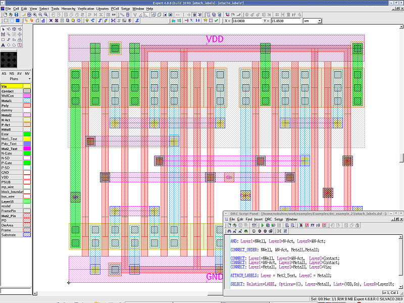
It attaches the "VDD" and "Sn" nodes to geometries of the Metal2 layer by the ATTACH_LABELS statement.
The Metal1 layer and the Metal2 layer are connected with the Via layer by the CONNECT statement.
Then the Metal1 layer shapes with the "VDD" and "Sn" nodes are selected by the SELECT statement, and the selected shapes are created in Layer15, shown in green color in Attache_labels.png .
To learn more about Guardian DRC , the different commands and their syntax as well as the different setup options, see the Guardian DRC user manual "guardian_users1.pdf" located in lib/expert/4.14.0.R/docs/ in your installation area.
attach_labels.dsf
AND: Layer1=NWell, Layer2=N-Act, LayerR=&N-Act;

CONNECT_ORDER: NWell, &N-Act, Metal1,Metal2;

CONNECT: Layer1=NWell, Layer2=&N-Act,  LayerC=Contact;
CONNECT: Layer1=&N-Act, Layer2=Metal1, LayerC=Contact;
CONNECT: Layer1=Metal1, Layer2=Metal2, LayerC=Via;

ATTACH_LABELS: Layer = Met2_Text, LayerC = Metal2;

SELECT: Relation=LABEL, Options=(C), Layer=Metal1, List=(VDD,Sn), LayerR=Layer15;