001_select_inside : Select Operation With INSIDE Option
Minimum Required Version
: Expert 4.14.0.R, Guardian 4.14.0.R
Guardian DRC contains a SELECT statement that can be used to identify layout objects for a particular design rule check. The SELECT statement has many different forms; each signified by a different relational options. In this example, the INSIDE relational option is demonstrated with the SELECT operation.
Loading the Example Circuit and DRC Script
Open Expert, load the example circuit in the Expert project drc_ex12.eld, and open the sample layout cell named DFF. This sample layout contains a D-Flip Flop circuit which will be used to show the operation of the SELECT command. Next, the DRC script containing the appropriate rule set must be loaded by selecting the Expert menu Verification->DRC->DRC Script Panel. From the script panel, select File->Open and browse to the DRC rule set for this example, named drc_ex12.dsf.
Syntax
The syntax for the SELECT command with relation=INSIDE can be seen several times in the example DRC script and is also reproduced below:
   SELECT: Relation=INSIDE,
          [Options=([C][,NOT]),]
           Layer1=< layer1 identifier >,
           Layer2=< layer2 identifier >,
           LayerR=< result layer identifier >;
One of the possible options settings shown above is Options=(C) , in which the selection operation will be based on electrical connectivity information. Using Options=(NOT) will perform the selection operation if the conditions of the select command are not met. This option is used in the first two rule SELECT operations in the example script to select any VIA shapes that are NOT completely inside of METAL1 and METAL2, respectively, and flag them as errors in the error database by using the COPY command, which will copy the resulting geometries "via_no_m1" and "via_no_m2" to ID="<text>" , which contains the rule name or description.
The last two commands in the DRC script are used to create the scratch layer "ntap" that identifies all N+ doped active regions inside N_WELL, and can be used with further commands to implement rules that would check for transistor spacing to well tie regions, or to check that all wells have a well tie connected to a specified node. The "ntap" scratch layer, along with other scratch layers generated by the Guardian commands are written back to the layout in this example deck. To prevent any scratch layers from being written to the layout, the command: update_layout:new=yes; can be changed to update_layout:new=no.
DRC Output
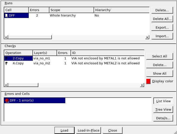
To run the example DRC script, select the menu item DRC->Run from the DRC script panel with the drc_ex12.dsf script loaded. Once the DRC is complete, return to the Expert window containing the layout and select Verification->DRC->Errors->Load Errors. This will open the error window containing all errors found by the DRC script. As seen in Figure1 , there are a total of two errors; one for VIA/METAL1 violation and the other for VIA/METAL2 violation.
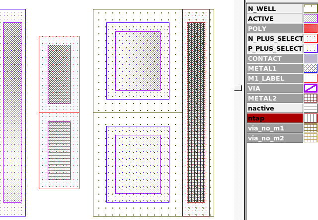
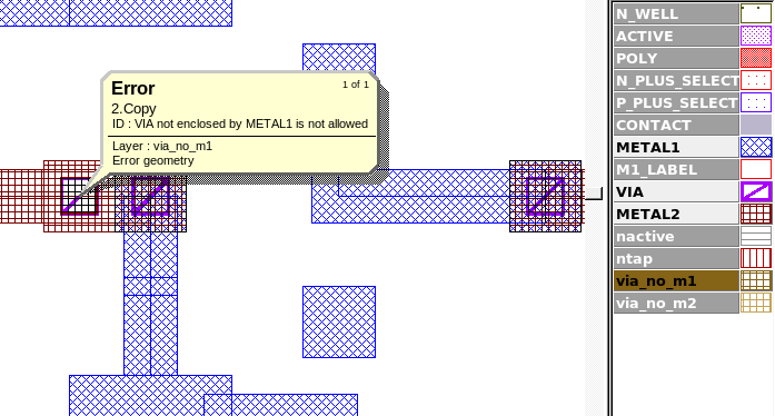
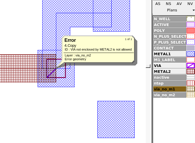
By selecting the first error and clicking on the "Load" button in the error window and selecting the Expert menu item Verification->DRC->Errors->First Error the layout view will be taken to the first violation as seen in Figure2 , which shows a VIA shape with only METAL2 present. Following the same steps for the next error type will show Figure3 , which is a violation caused by a VIA geometery only partially covered by METAL2. Figure4 shows the scratch layer "ntap" that was generated by the DRC script commands, which can be used as the primary layer in other DRC rule checks that focus on this type of well tap.
select_inside_ex12.dsf
											/////////////////////////////////////
//       EXAMPLE DRC SCRIPT        //
/////////////////////////////////////
Layers:
    N_WELL		(42, 0)
,   ACTIVE		(43, 0)
,   P_PLUS_SELECT	(44, 0)
,   N_PLUS_SELECT	(45, 0)
,   POLY		(46, 0)
,   METAL1		(49, 0)
,   VIA			(50, 0)
,   METAL2		(51, 0)
;
update_layout:new=yes;

//Select any VIA not covered by METAL1 and output an error message
Select: Relation=INSIDE, Options=(NOT),Layer1=VIA, Layer2=METAL1, LayerR=via_no_m1;
Copy: Layer=via_no_m1, ID="VIA not enclosed by METAL1 is not allowed";

//Select any VIA not covered by METAL2 and output an error message
Select: Relation=INSIDE, Options=(NOT),Layer1=VIA, Layer2=METAL2, LayerR=via_no_m2;
Copy: Layer=via_no_m2, ID="VIA not enclosed by METAL2 is not allowed";

//Create "nactive" layer
And: Layer1=ACTIVE, Layer2=N_PLUS_SELECT, LayerR=nactive;
//Create "ntap" layer
Select: Relation=INSIDE, Layer1=nactive, Layer2=N_WELL, LayerR=ntap;