002_indistance : InDistance Operation
Minimum Required Version
: Expert 4.14.0.R, Guardian 4.14.0.R
This example will demonstrate how the Guardian DRC tool can be used to measure the InDistance of layout objects which contain other objects.
1. Preliminary steps
To run this example, open a Guardian DRC session and choose File->Open to load the project "drc_ex08.eld" downloaded. Then open the top cell drc_ex08 using the Cell->Open... menu.
2. InDistance command for error detection
Some common rules that uses an InDistance command, are:
- Min contact enclosure by Metal1
- Min Poly extension beyond the Active region
- Min NPLUS overlap of Active region
The InDistance command is used to measure the inner distance of a layer1 , which is located inside a layer2 . It checks the admissible distance between the outer surfaces of regions from the first input layer and inner surfaces of regions from the second input layer.
Guardian DRC can be used to implement the InDistance checks.
The syntax for this rule is:
   InDistance: Layer1= < input layer identifier1 >,
               Layer2= < input layer identifier2 >,
               Value= < value >, Type= < check type >,
               LayerR1= < result layer identifier1 >,
               LayerR2= < result layer identifier2 >,
               Options = (list of check options),
               ID = < error identifier >;
in which:
- Layer1 is the inside layer name being measured
- Layer2 is the outside layer name being measured
- Value is the value in um of the measurement
- Type can be greater than, less than, (>, <, ==, !=, ...)
- LayerR1 is the layer name in which the geometries of layer1 in violation of the rule would be saved
- LayerR2 is the layer name in which the geometries of layer2 in violation of the rule would be saved
- Options is the list of additional option to the check, for example, the width between parallel segment only is being measured
- ID is the error message that would be display and listed in the log when the error occur (ex: Min M1 enclosure of CNT is 0.4um)
Figure 1 illustrates the syntax that can be used to implement such a task.
Some additional commands can be used to increase the selectivity of the check being done. The option T , if enabled, would threat polygons touching as an error.
More options can be used. A detailed description of all options can be found in the Guardian DRC user manual section 2.3.9.1: Common Syntax: Parameters and Options. Section 2.3.9.5 describes the InDistance command. The user manual "guardian_users1.pdf" can be found in lib/expert/4.14.0.R/docs/ in your installation area.
Some options are not allowed for certain DRC checks. For the "InDistance" operation, the options: D, U, IS, N, N' ( Acute adjacency, Obtuse adjacency, Self intersecting, Notch, and Notch Only ) are not allowed.
3. Experimenting with the InDistance command
Once all the example files have been downloaded and the preliminary steps described in 1.0 are completed the user can follow the instructions below:
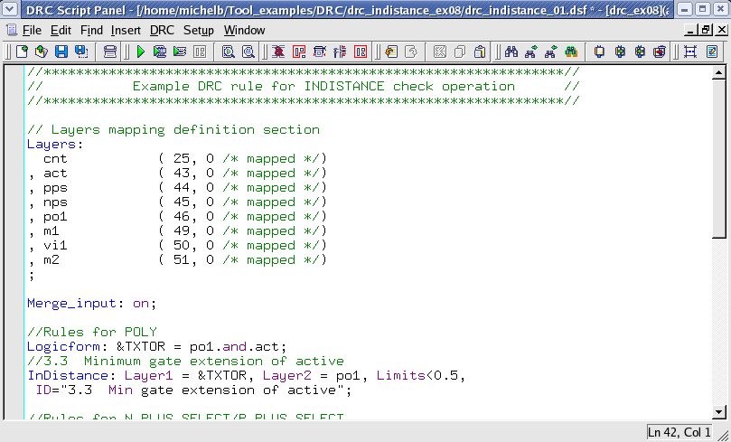
- Choose Verification->DRC->DRC Script panel . In this new window, choose File->Open... and select "drc_indistance_01.dsf".
- Press DRC->Run
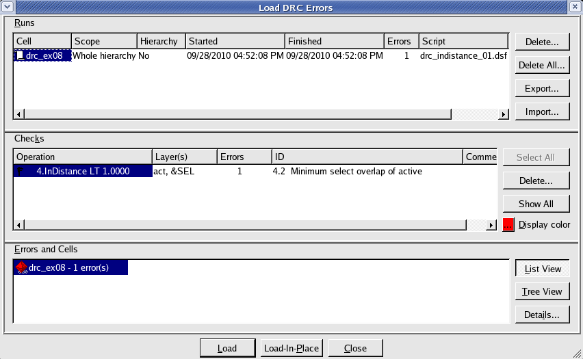
- To inspect the errors, choose Verification->DRC->Errors->Load errors... you should get a window as shown in Figure 2.
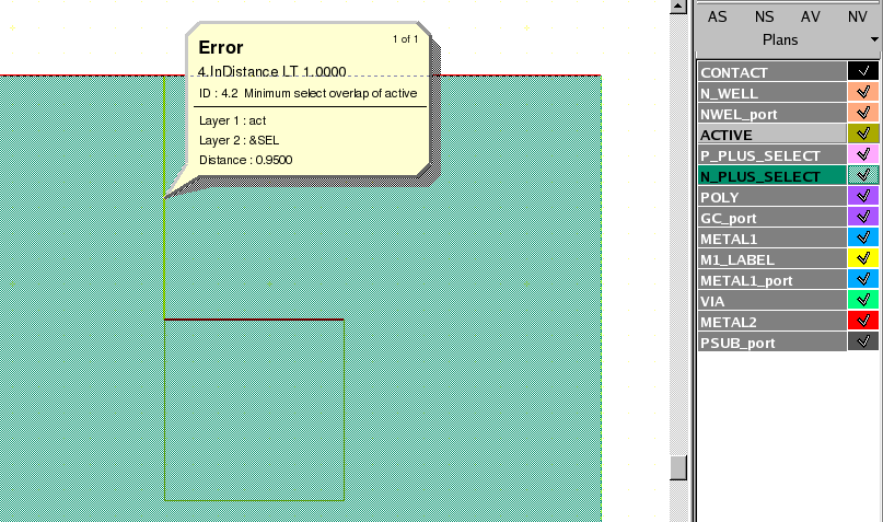
- Select the check and press the Load button located at the bottom of the window. Then choose Verification->DRC->Errors->First error to display the error in the layout, as shown in Figure 3 .
- To unload the error choose Verification->DRC->Errors->Unload errors .
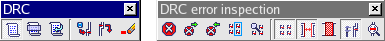
Note that these two toolbars can be used to access the DRC menu command. To turn the visibility of the toolbar ON and OFF, choose View->Toolbars and select DRC and DRC error inspection.
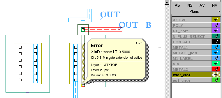
To understand the effect of the LayerR1 and LayerR2 , open the layout cell "indist_2" , and run the DRC script "drc_indistance_02.dsf" . You should see one DRC error and the creation of two new layers txtor_error and po1_error , as shown in figure 5 .
Guardian DRC can also be launched from within the Expert layout editor. Within an Expert session, follow the steps described in 1.0 to open the eld file. Then choose Verification->DRC->DRC Script panel. In this new window, choose File->Open... and select desired DRC script. The rest of the steps are identical to the Guardian DRC flow.
drc_indistance_01.dsf
											//****************************************************************//
//           Example DRC rule for INDISTANCE check operation      //
//****************************************************************//

// Layers mapping definition section
Layers:
  cnt		( 25, 0	/* mapped */)
, act		( 43, 0	/* mapped */)
, pps		( 44, 0	/* mapped */)
, nps		( 45, 0	/* mapped */)
, po1           ( 46, 0	/* mapped */)
, m1            ( 49, 0	/* mapped */)
, vi1           ( 50, 0	/* mapped */)
, m2            ( 51, 0	/* mapped */)
;

Merge_input: on;

//Rules for POLY
Logicform: &TXTOR = po1.and.act;
//3.3  Minimum gate extension of active
InDistance: Layer1 = &TXTOR, Layer2 = po1, Limits<0.5,
 ID="3.3  Min gate extension of active";

//Rules for N_PLUS_SELECT/P_PLUS_SELECT
Logicform: &SEL=nps.or.pps;
//4.2  Minimum select overlap of active
InDistance: Layer1 = act, Layer2 = &SEL, Limits<1  , Options=(T),
 ID="4.2  Minimum select overlap of active";
//4.3  Minimum select overlap of contact
InDistance: Layer1 = cnt, Layer2 = &SEL, Limits<0.5 , Options=(T),
 ID="4.3  Min select overlap of contact";

//Rules for CONTACT
//5.2  Minimum poly overlap
InDistance: Layer1 = cnt, Layer2 = po1, Limits<0.5  , Options=(T),
 ID="5.2  Min poly overlap of contact";
//7.3  Minimum overlap of any contact
InDistance: Layer1 = cnt, Layer2 = m1, Limits<0.1, Options=(T),
 ID="7.3  Min Metal1 overlap of contact";


// END of DRC check
drc_indistance_02.dsf
											//****************************************************************//
//           Example DRC rule for INDISTANCE check operation      //
//****************************************************************//

// Layers mapping definition section
Layers:
  cnt		( 25, 0	/* mapped */)
, act		( 43, 0	/* mapped */)
, pps		( 44, 0	/* mapped */)
, nps		( 45, 0	/* mapped */)
, po1           ( 46, 0	/* mapped */)
, m1            ( 49, 0	/* mapped */)
, vi1           ( 50, 0	/* mapped */)
, m2            ( 51, 0	/* mapped */)
;

Merge_input: on;

//Rules for POLY
Logicform: &TXTOR = po1.and.act;
//3.3  Minimum gate extension of active
InDistance: Layer1 = &TXTOR, Layer2 = po1, Limits<0.5,
LayerR1=txtor_eror, LayerR2=po1_error,
 ID="3.3  Min gate extension of active";


// END of DRC check