001_and : AND Operation Between Two Layers
Minimum Required Version
: Expert 4.14.0.R, Guardian 4.14.0.R
This example will demonstrate how a Boolean AND function can be used in Guardian DRC to detect Design Rule Check (DRC) errors or to derive some additional layers from the current drawing layers in the layout using Expert.
1. Preliminary steps
To run this example, open a Guardian DRC session and choose File->Open to load the project "drc_and_ex01.eld" . Open the top cell SWG_DRC using the Cell->Open... menu.
2. Boolean AND for error detection
In most Design Rule Check foundry files, there is a certain combination of drawing layers that are not allowed to overlap. In such a case, a DRC error needs to be flagged and reported to the designer. For example, certain processes do not allow contacts and vias to be stacked. A rule would therefore have to be written to detect each contact/via that is overlapping. A simple AND function of the two layers performed in a DRC deck would detect such errors.
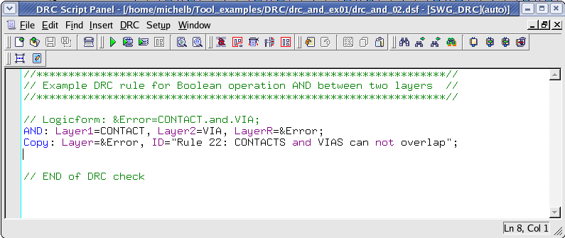
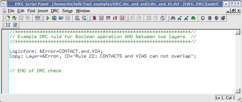
Guardian DRC offers two different syntax options to complete this task. Figure 1 , illustrates the first syntax, and Figure 2 , shows an alternative syntax.
The first syntax has a certain advantage over the second one, as it allows the use of parenthesis for a combination of multiple layers or functions.
A user could write:
             Logicform: &Error= (CONTACT.and.VIA).or.(VIA.and.VIA2);
            . . .
The same rule check in the second syntax would be written:
             AND: Layer1=CONTACT, Layer2=VIA,   LayerR=&tmp1;
             AND: Layer1=VIA,     Layer2=VIA2,  LayerR=&tmp2;
             OR : Layer1=&tmp1,   Layer2=&tmp2, LayerR=&Error;
            . . .
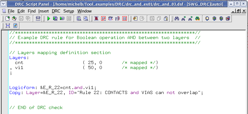
In Figure 3 we illustrate the same rule as in Figure 1 with the exception that here a layer mapping is being used. Therefore, the layer name in the Guardian DRC rule deck does not have to match the layer name in the layout. This would allow the rule deck to be run on a GDS file for which layer names are not provided.
3. Boolean AND for layer derivation
A simple AND function could also be useful in performing layer derivation, for example, assuming that an existing layout needs to be ported to a new technology. However, the new technology requires a marking layer on the gate of the MOS transistor. This marking layer was non-existent in the current layout. Using a logical AND as shown in Figure 4 on all the layout database, a user could derive the new layer and save a considerable amount of time of layout editing.
4. Experimenting with Boolean AND function
Once all the example files have been downloaded and the preliminary steps described in 1.0 are completed, complete the following steps:
- Choose Verification->DRC->DRC Script panel . In this new window, choose File->Open... and select "drc_and_01.dsf".
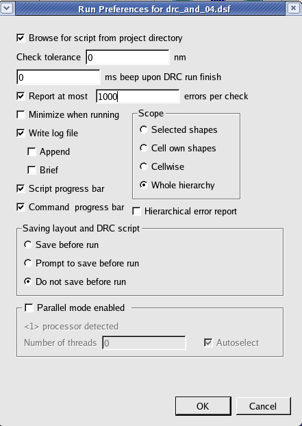
- In the same window, choose Setup->Current DRC script run preferences... and set the options as shown in Figure5 .
- Accept the changes and press DRC->Run
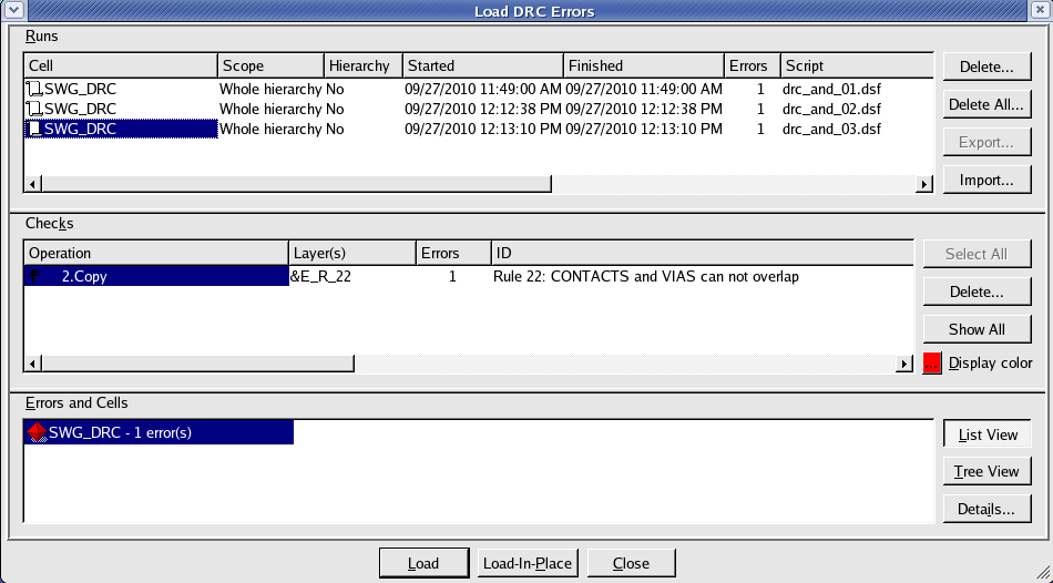
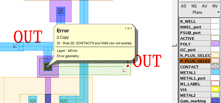
- To inspect the errors, choose Verification->DRC->Errors->Load errors... and press the Load button located at the bottom of the window. Then choose Verification->DRC->Errors->First error to display the error in the layout, as shown in Figure 6 .
- To unload the error choose Verification->DRC->Errors->Unload errors .
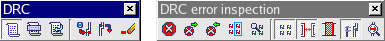
Note these two toolbars can be used to access the DRC menu command. To turn the visibility of the toolbar ON and OFF, choose View->Toolbars and select DRC and DRC error inspection.
The scripts "drc_and_02.dsf" , and "drc_and_03.dsf" , can be run following the same steps described above.
After a few runs, the Load DRC Errors window will display more than one DRC run in its log. The user can then compare results to a previous DRC run.
Guardian DRC can also be launched from within the Expert layout editor. To run the fourth script "drc_and_04.dsf" , open an Expert session and follow the steps described in 1.0 to open the eld file. Then choose Verification->DRC->DRC Script panel . In this new window, choose File->Open... and select "drc_and_04.dsf" . Press run. This should add a new layer to the layout named "Gate_marking", which corresponds to the gate of the MOS device.
To learn more about Guardian DRC, the different commands and their syntax as well as the different setup options, see the Guardian DRC user manual "guardian_users1.pdf" located in lib/expert/4.14.0.R/docs/ in your installation area.
drc_and_01.dsf
											//****************************************************************//
// Example DRC rule for Boolean operation AND between two layers  //
//****************************************************************//

Logicform: &Error=CONTACT.and.VIA;
Copy: Layer=&Error, ID="Rule 22: CONTACTS and VIAS can not overlap";


// END of DRC check
drc_and_02.dsf
											//****************************************************************//
// Example DRC rule for Boolean operation AND between two layers  //
//****************************************************************//

// Logicform: &Error=CONTACT.and.VIA;
AND: Layer1=CONTACT, Layer2=VIA, LayerR=&Error;
Copy: Layer=&Error, ID="Rule 22: CONTACTS and VIAS can not overlap";


// END of DRC check
drc_and_03.dsf
											//****************************************************************//
// Example DRC rule for Boolean operation AND between two layers  //
//****************************************************************//

// Layers mapping definition section
Layers:
  cnt                     ( 25, 0	/* mapped */)
, vi1                     ( 50, 0 	/* mapped */)
;


Logicform: &E_R_22=cnt.and.vi1;
Copy: Layer=&E_R_22, ID="Rule 22: CONTACTS and VIAS can not overlap";


// END of DRC check
drc_and_04.dsf
											//****************************************************************//
// Example DRC rule for Boolean operation AND between two layers  //
//****************************************************************//

// Layers mapping definition section
Layers:
  cnt                     ( 25, 0	/* mapped */)
, act                     ( 43, 0 	/* mapped */)
, po1                     ( 46, 0 	/* mapped */)
, vi1                     ( 50, 0 	/* mapped */)
;


Logicform: Gate_marking = act.and.po1;


// END of DRC check