008_current_starved_VCO : Current Starved VCO schematic
Minimum Required Versions: Gateway 2.12.8.R, SmartSpice 3.16.11.R
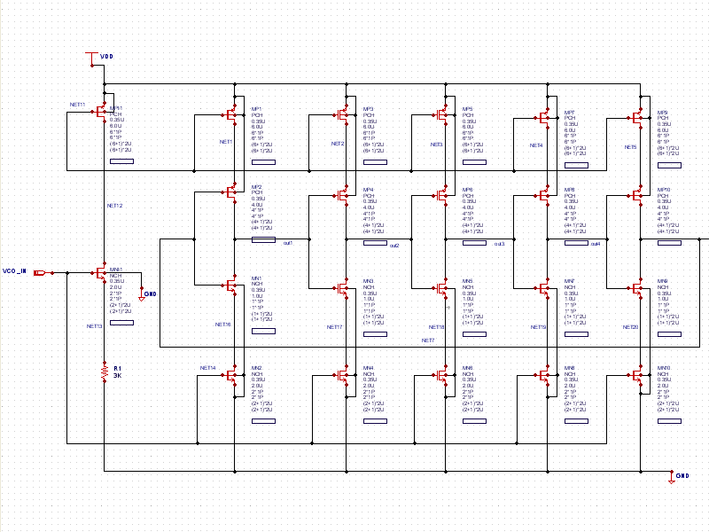
Example 8 demonstrates a 5-Stage VCO design using a level=54 BSim4 SmartSpice model (see schematic.png ). The circuit can be used to generate clock signals for driving PLLs and other circuits. Using this design technique (current-starved), the current is controlled in each stage of the ring oscillator, achieving a wide frequency of operation. This design operates up to approximately 350MHz and the output is clamped to 1.4V.
The control file ( current_starved_VCO.ctr) shows the circuit to be run twice. The first time, a sine wave input at 4MHz is connected. Also, the: .PARAM VDD=2.2V GND=0.0V t=1.0us statement is defined so that any of these parameters may be changeable throughout the design by changing the value in the .PARAM statement. Since t=1.0us is defined, the time parameters in statements can be a function of t instead of using discrete times. In the example, the transient statement is set to run to time t, or to 1.0us.
After the first run, the input deck hits the .ALTER statement and then processes the statements that follow. In this example, the sinusoidal VIN input is replaced with a PWL piecewise linear voltage source defined in time-voltage (t, v) pairs. The values are defined in terms of t and VDD, respectively.
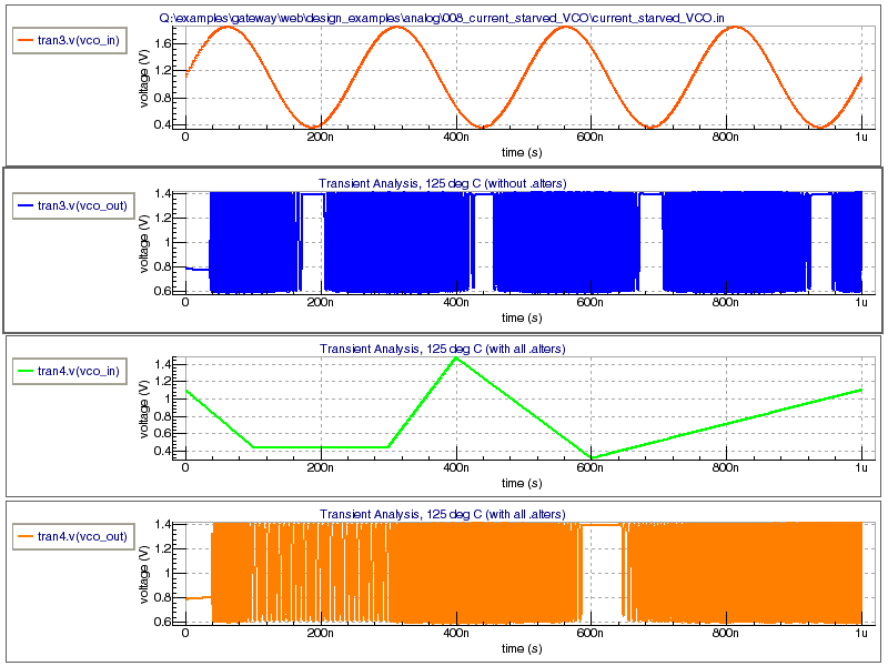
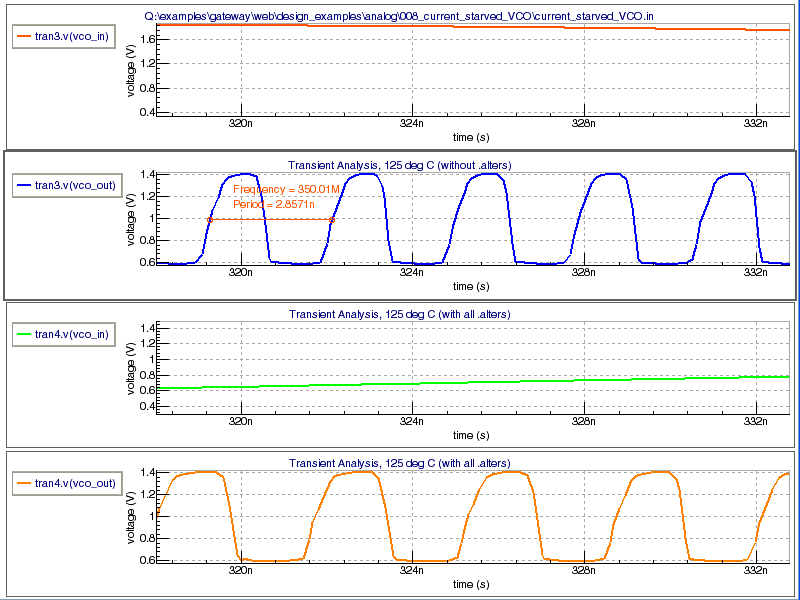
Upon completing the simulations, the wave forms are displayed (see waveforms.png ). Right clicking the plot and choosing to split the charts will make the charts look like the screenshot of the waveforms. By zooming in and using the period tool, the maximum operational frequency can be determined and displayed (see operational_frequency.png ).
current_starved_VCO.ctr
*5-Stage VCO with resistor for Typical/Typical Process .OPTIONS ACCT NOMOD RELTOL=0.001 STOPCONT .PARAM VDD=2.2V GND=0.0V t=1.0us .TEMP 125 .model DIO D .TRAN 0.1ns t VPWR VDD 0 VDD VGND GND 0 GND VIN VCO_IN 0 SIN ( 'VDD/2' 0.75 4MEGHz ) *VIN VCO_IN 0 SIN (0 0.1 200KHz ) *IN VCO_IN 0 PWL ( 0 0 4us 'VDD/5' 5us 'VDD/5' 6us 'VDD/6' 7us 'VDD/7' 8us 'VDD/8' 10us 'VDD/10' ) .MODEL NCH NMOS ( +LEVEL = 54 VERSION = 4.5 BINUNIT = 1 +PARAMCHK = 1 MOBMOD = 1 RDSMOD = 0 +IGCMOD = 1 IGBMOD = 1 CAPMOD = 2 +RGATEMOD = 0 RBODYMOD = 0 TRNQSMOD = 0 +ACNQSMOD = 0 FNOIMOD = 1 TNOIMOD = 0 +DIOMOD = 2 PERMOD = 1 GEOMOD = 0 +EPSROX = 3.9 TOXE = 2.3e-09 TOXP = 1.872e-09 +TOXM = 2.3e-09 DTOX = 4.28e-10 XJ = 1.2e-07 +NDEP = 1.7e+17 NGATE = 0 NSD = 1e+20 +RSH = 0 RSHG = 0.1 VTH0 = 0.123827 +VFB = -1 PHIN = 0 K1 = 0.411566 +K2 = -0.138322 K3 = 0.00339117 K3B = 0.128115 +W0 = 1.44268e-05 LPE0 = 1.74e-07 LPEB = 0 +DVT0 = 0.161688 DVT1 = 0.19166 DVT2 = 0 +DVTP0 = 0 DVTP1 = 0 DVT0W = 0 +DVT1W = 0 DVT2W = -0.032 U0 = 421.386 +UA = 1e-10 UB = 2.53382e-18 UC = -1e-10 +EU = 1.67 VSAT = 143029 A0 = 2 +AGS = 1.54051 B0 = -3.78667e-08 B1 = -1e-07 +KETA = 0.05 A1 = 0 A2 = 1 +WINT = -2.62512e-09 LINT = 8.48093e-09 DWG = -5.66202e-09 +DWB = -1.84828e-08 VOFF = -0.136325 VOFFL = 0 +MINV = 0 NFACTOR = 1.92074 ETA0 = 0.00391336 +ETAB = -0.00222443 DSUB = 0.775449 CIT = 0 +CDSC = 0.00024 CDSCB = 0 CDSCD = 0 +PCLM = 0.351808 PDIBLC1 = 0.00811998 PDIBLC2 = 0.00161876 +PDIBLCB = -5.24942e-05 DROUT = 0.103197 PSCBE1 = 1e+09 +PSCBE2 = 1e-09 PVAG = 4.1257 DELTA = 0.03 +FPROUT = 0 PDITS = 0 PDITSL = 0 +PDITSD = 0 LAMBDA = 0 VTL = 205000 +LC = 0 XN = 3 RDSW = 100 +RDSWMIN = 100 RDW = 100 RDWMIN = 0 +RSW = 100 RSWMIN = 0 PRWG = 0.1 +PRWB = -0.001 WR = 1 ALPHA0 = 0 +ALPHA1 = 0 BETA0 = 30 AGIDL = 1.108e-08 +BGIDL = 1.39e+09 CGIDL = 0.2963 EGIDL = 0.944 +AIGBACC = 0.01198 BIGBACC = 0.008013 CIGBACC = 0.6256 +NIGBACC = 4.397 AIGBINV = 0.0153 BIGBINV = 0.004852 +CIGBINV = 0.001 EIGBINV = 1.1 NIGBINV = 1.6 +AIGC = 0.01138 BIGC = 0.001879 CIGC = 0.0001 +AIGSD = 0.009883 BIGSD = 0.001269 CIGSD = 0.1554 +DLCIG = 1.8e-08 NIGC = 1 POXEDGE = 1 +PIGCD = 2.5 NTOX = 1 TOXREF = 2.25e-09 +XPART = 0 CGSL = 2.2e-10 CGDL = 2.2e-10 +CKAPPAS = 0.6 CKAPPAD = 0.6 CLC = 1e-07 +CLE = 0.6 DLC = 0 DWC = 0 +VFBCV = -1 NOFF = 1 VOFFCV = 0 +ACDE = 1 MOIN = 15 XRCRG1 = 12 +XRCRG2 = 1 RBPB = 50 RBPD = 50 +RBPS = 50 RBDB = 50 RBSB = 50 +GBMIN = 1e-12 NOIC = 8.75 EM = 4.1e+07 +AF = 1 EF = 1 KF = 0 +NTNOI = 1 TNOIA = 1.5 TNOIB = 3.5 +RNOIA = 0.577 RNOIB = 0.37 DMCG = 0 +DMCI = 0 DMDG = 0 DMCGT = 0 +DWJ = 0 XGW = 0 XGL = 0 +XL = 0 XW = 0 NGCON = 1 +IJTHSREV = 0.001691 IJTHDREV = 0.1 IJTHSFWD = 0.003445 +IJTHDFWD = 0.1 XJBVS = 1 XJBVD = 1 +BVS = 11.47 BVD = 10 JSS = 2.335e-07 +JSD = 0.0001 JSWS = 7.033e-14 JSWD = 0 +JSWGS = 3.2986e-14 JSWGD = 0 CJS = 0.00107 +MJS = 0.29 MJSWS = 0.33 CJSWS = 1.26e-10 +CJSWGS = 2.31e-10 MJSWGS = 0.33 PBS = 0.61 +PBSWS = 1 PBSWGS = 0.6 TNOM = 27 +UTE = -2 KT1 = -0.283442 KT1L = 8.28579e-09 +KT2 = 0.0024214 UA1 = 1.08382e-09 UB1 = -2.09558e-18 +UC1 = 0.067 AT = 1246.69 PRT = 0 +NJS = 1 NJD = 1 XTIS = 3 +XTID = 3 TPB = 0 TPBSW = 0 +TPBSWG = 0 TCJ = 0 TCJSW = 0 +TCJSWG = 0 SAref = 1e-06 SBref = 1e-06 +WLOD = 0 KU0 = 0 KVSAT = 0 +TKU0 = 0 LKU0 = 0 WKU0 = 0 +LLODKU0 = 0 WLODKU0 = 0 KVTH0 = 0 +LKVTH0 = 0 WKVTH0 = 0 LLODVTH = 0 +WLODVTH = 0 STK2 = 0 LODK2 = 1 +STETA0 = 0 LODETA0 = 1 WL = 0 +WLN = 1 WW = 0 WWN = 1 +WWL = 0 LL = 0 LLN = 1 +LW = 0 LWN = 1 LWL = 0 +LLC = 0 LWC = 0 LWLC = 0 +WLC = 0 WWC = 0 WWLC = 0 +WMAX = 1e-05 WMIN = 1.3e-07 LMAX = 1e-05 +LMIN = 9e-08 PVTH0 = -0.000997676 PRDSW = 0.000527959 +PK1 = 0.001 PK2 = 0.000101904 PUA = -3.01504e-11 +CGSO = 5e-11 CGDO = 5e-11 CGBO = 0 +PKETA = -0.001 PVSAT = -721.313 ) .MODEL PCH PMOS ( +LEVEL = 54 VERSION = 4.5 BINUNIT = 1 +PARAMCHK = 1 MOBMOD = 1 RDSMOD = 0 +IGCMOD = 1 IGBMOD = 1 CAPMOD = 2 +RGATEMOD = 0 RBODYMOD = 0 TRNQSMOD = 0 +ACNQSMOD = 0 FNOIMOD = 1 TNOIMOD = 0 +DIOMOD = 2 PERMOD = 1 GEOMOD = 0 +EPSROX = 3.9 TOXE = 2.43e-09 TOXP = 1.891e-09 +TOXM = 2.43e-09 DTOX = 5.39e-10 XJ = 1.2e-07 +NDEP = 3.6e+16 NGATE = 0 NSD = 1e+20 +RSH = 0 RSHG = 0.1 VTH0 = -0.084248 +VFB = -1 PHIN = 0 K1 = 0.0646181 +K2 = 0.0551608 K3 = 0 K3B = 10 +W0 = 0 LPE0 = 1.74e-07 LPEB = 0 +DVT0 = 0 DVT1 = 0.0390828 DVT2 = 5e-10 +DVTP0 = 0 DVTP1 = 0 DVT0W = 0.177904 +DVT1W = 601592 DVT2W = 0.29259 U0 = 116.4 +UA = 1.88952e-09 UB = 1e-21 UC = -1e-10 +EU = 1.67 VSAT = 61149.6 A0 = 2 +AGS = 1.15498 B0 = 5.18192e-07 B1 = 1e-07 +KETA = 0 A1 = 0 A2 = 1 +WINT = 0 LINT = 0 DWG = -2.75924e-08 +DWB = -1.34218e-10 VOFF = -0.131222 VOFFL = 0 +MINV = 0 NFACTOR = 2 ETA0 = 0.903788 +ETAB = -0.000419823 DSUB = 1 CIT = 0 +CDSC = 0.00024 CDSCB = 0 CDSCD = 0 +PCLM = 0.1 PDIBLC1 = 0.00107381 PDIBLC2 = 1e-05 +PDIBLCB = -0.000123175 DROUT = 0.357852 PSCBE1 = 1e+09 +PSCBE2 = 1e-09 PVAG = 8.51905 DELTA = 0.03 +FPROUT = 0 PDITS = 0 PDITSL = 0 +PDITSD = 0 LAMBDA = 0 VTL = 205000 +LC = 0 XN = 3 RDSW = 1000 +RDSWMIN = 100 RDW = 100 RDWMIN = 0 +RSW = 100 RSWMIN = 0 PRWG = 0.1 +PRWB = -0.001 WR = 1 ALPHA0 = 0 +ALPHA1 = 0 BETA0 = 30 AGIDL = 4.432e-09 +BGIDL = 4.808e+09 CGIDL = 0.009173 EGIDL = -2.18 +AIGBACC = 0.01103 BIGBACC = 0.006761 CIGBACC = 0.577 +NIGBACC = 4.396 AIGBINV = 0.009466 BIGBINV = 0.00234 +CIGBINV = 0.001832 EIGBINV = 1.633 NIGBINV = 3.124 +AIGC = 0.00679 BIGC = 0.0008875 CIGC = 0.0006343 +AIGSD = 0.005652 BIGSD = 7.805e-05 CIGSD = 0.01803 +DLCIG = 3.2e-08 NIGC = 0.7925 POXEDGE = 1 +PIGCD = 1 NTOX = 1 TOXREF = 2.45e-09 +XPART = 0 CGSL = 2e-10 CGDL = 2e-10 +CKAPPAS = 0.6 CKAPPAD = 0.6 CLC = 1e-07 +CLE = 0.6 DLC = 0 DWC = 0 +VFBCV = -1 NOFF = 1 VOFFCV = 0 +XRCRG1 = 12 XRCRG2 = 1 RBPB = 50 +RBPD = 50 RBPS = 50 RBDB = 50 +RBSB = 50 GBMIN = 1e-12 NOIC = 8.75 +EM = 4.1e+07 AF = 1 EF = 1 +KF = 0 NTNOI = 1 TNOIA = 1.5 +TNOIB = 3.5 RNOIA = 0.577 RNOIB = 0.37 +DMCG = 0 DMCI = 0 DMDG = 0 +DMCGT = 0 DWJ = 0 XGW = 0 +XGL = 0 XL = 0 XW = 0 +NGCON = 1 IJTHSREV = 0.002175 IJTHDREV = 0.1 +IJTHSFWD = 0.0035 IJTHDFWD = 0.1 XJBVS = 1 +XJBVD = 1 BVS = 8.964 BVD = 10 +JSS = 1.995e-07 JSD = 0.0001 JSWS = 1.092e-13 +JSWD = 0 JSWGS = 1e-13 JSWGD = 0 +CJS = 0.00126 MJS = 0.31 MJSWS = 0.33 +CJSWS = 5e-10 CJSWGS = 5e-10 MJSWGS = 0.33 +PBS = 0.73 PBSWS = 1 PBSWGS = 0.6 +TNOM = 27 UTE = -2 KT1 = -0.278301 +KT1L = -3.24611e-12 KT2 = 0.0146989 UA1 = -1.02398e-09 +UB1 = -2.61056e-18 UC1 = 0.067 AT = 33000 +PRT = 0 NJS = 1 NJD = 1 +XTIS = 3 XTID = 3 TPB = 0 +TPBSW = 0 TPBSWG = 0 TCJ = 0 +TCJSW = 0 TCJSWG = 0 SAref = 1e-06 +SBref = 1e-06 WLOD = 0 KU0 = 0 +KVSAT = 0 TKU0 = 0 LKU0 = 0 +WKU0 = 0 LLODKU0 = 0 WLODKU0 = 0 +KVTH0 = 0 LKVTH0 = 0 WKVTH0 = 0 +LLODVTH = 0 WLODVTH = 0 STK2 = 0 +LODK2 = 1 STETA0 = 0 LODETA0 = 1 +WL = 0 WLN = 1 WW = 0 +WWN = 1 WWL = 0 LL = 0 +LLN = 1 LW = 0 LWN = 1 +LWL = 0 LLC = 0 LWC = 0 +LWLC = 0 WLC = 0 WWC = 0 +WWLC = 0 WMAX = 1e-05 WMIN = 1.3e-07 +LMAX = 1e-05 LMIN = 9e-08 PVTH0 = -0.01 +PRDSW = 0 PK1 = -8.15738e-05 PK2 = -0.000211513 +PUA = -3.71012e-13 CGSO = 4.2e-11 CGDO = 4.2e-11 +CGBO = 0 PVSAT = 1000 ) $****************************************************** .ALTER *VIN VCO_IN 0 SIN ( 'VDD/3' 0.25 0.5MEGHz t/10 ) VIN VCO_IN 0 PWL ( 0 'VDD/2' '0.1*t' 'VDD/5' '0.3*t' 'VDD/5' '0.4*t' 'VDD/1.5' '0.6*t' 'VDD/7' 't' 'VDD/2' )