006_lvs : Guardian LVS verification tool
Minimum Required Versions: Expert 4.10.39.R & Gateway 2.12.32.R & Guardian 4.8.36.R & HIPEX 3.4.38.R
Guardian LVS (Layout Versus Schematic) netlist comparison tool compares two SPICE netlists. One of the compared netlists usually corresponds to the schematic of a circuit produced by a schematic editor (e.g. Gateway), which represents the circuit. The other netlist is extracted from the circuit layout by Guardian NET. It represents the actual physical layout of the circuit as produced by a layout editor (e.g. Expert).
1.1. Create SPICE netlist from Schematic
A SPICE netlist is created by selecting Layout->Netlist->Guardian in Gateway.
Steps to execute:
- Load ex017.workspace and open ex017.schlr.
- Execute Guardian by selecting Layout->Netlist .
1.2. Create SPICE netlist from the Layout
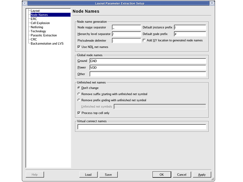
The global node names are set in the Layout Parameter Extraction Setup dialog. To open the Layout Parameter Extraction Setup, select Verification->Extraction->Setup . Then select the Node Names tab page. The global node names for power, ground and other nodes can be set (see lpe_setup.png ).
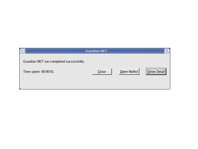
A SPICE netlist is created from the layout by selecting Verification->Extraction->HIPEX-Net->Run . The window of Guardian NET pops up after finishing the HIPEX-Net (see guardian_net.png ). It says "Guardian NET run completed successfully", and the netlist is created without problem.
To check the netlist, click the "Open Netlist" button.
Steps to execute:
- Load ex017.eld file and open ex017 cell.
- Execute the Run command by selecting Verification->Extraction->HIPEX-Net .
1.3. Compare two SPICE netlists
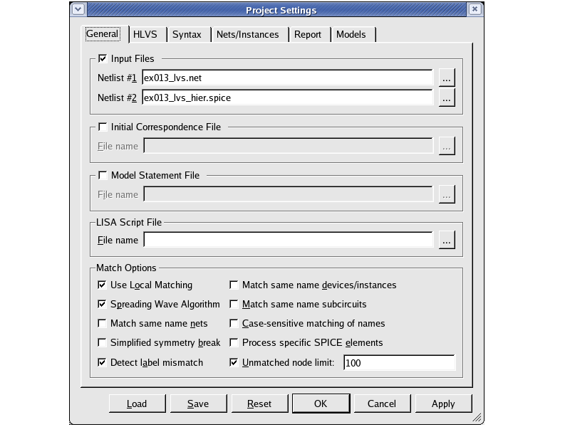
Launch Guardian LVS by selecting Verification->Extraction->LVS->launch LVS . A Guardian LVS dialog will open (see guardian_lvs.png ). It is necessary to set the project settings in the "Project Settings" dialog. To open it, select Setup->Project Settings or click the project setting button in the Action Toolbar (see project_settings.png ).
Steps to execute:
- Add two SPICE netlists to Input Files in the General tab.
The netlist has to be set as follows:
Netlist #1 ----- Netlist of the schematic
Netlist #2 ----- Netlist of the Layout
If the order of the two netlists is reversed, the cross probing is not executed. - Load the Guardian LVS project setting file ex017.gpr by clicking the Load button in the bottom of the Project Settings dialog.
- Execute the Run LVS command from the Action menu or by clicking the Run LVS button in the Action Toolbar.
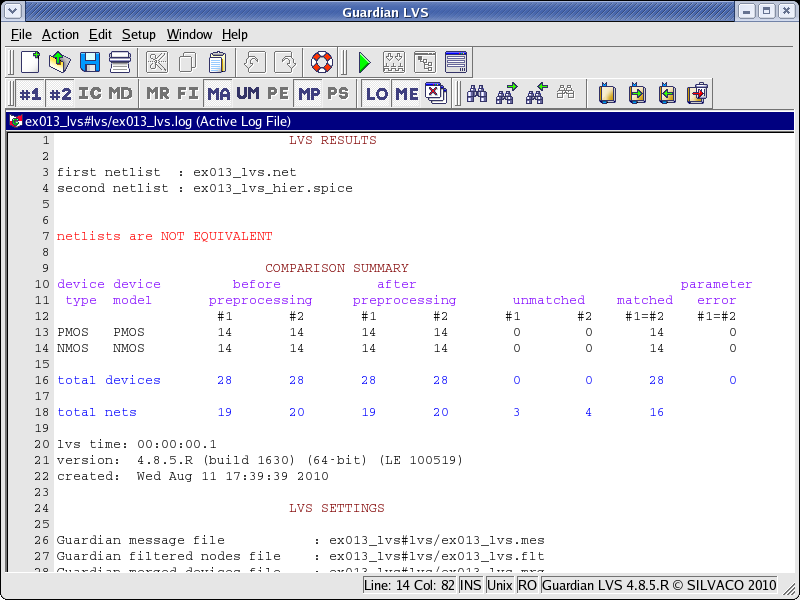
- The LVS result is displayed in the LVS log file.
Here is the example of the LVS result:
netlists are EQUIVALENT: Two netlists are logically equivalent.
netlists are NOT EQUIVALENT: Two netlists are not logically equivalent.
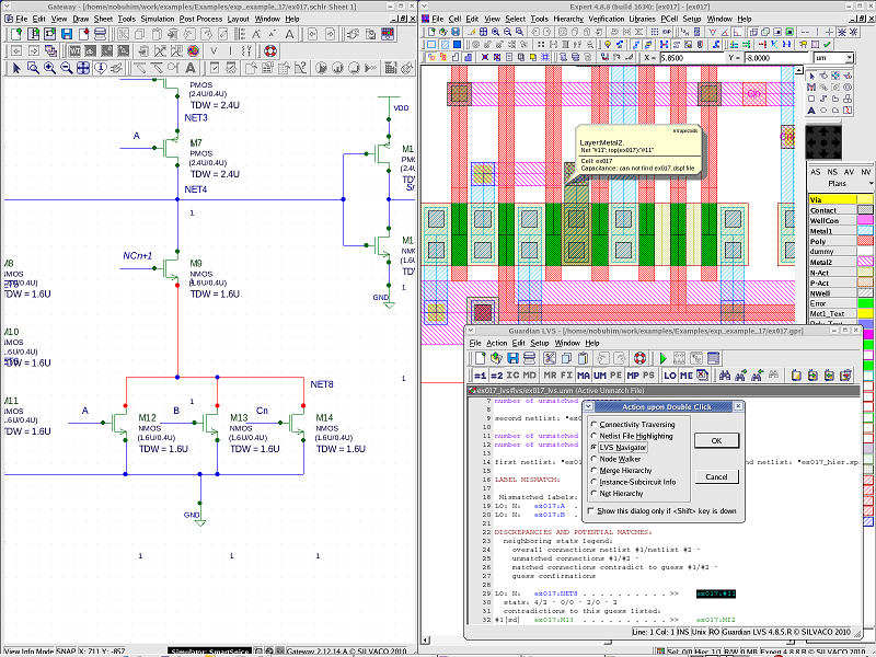
netlists are topologically EQUIVALENT, parameter errors are detected: Two netlists are logically equivalent, but it has a parameter errors. - Details of the error are in Unmatched file(UM) and Parameter Error file(PE) when there is an LVS error. When the node name in UM(PE) is double-clicked, cross probing between UM(PE) and Layout is executed. The LVS error part is highlighted in the Layout, so it is easy to find the LVS error.
- Guardian LVS is now able to cross probe between Schematic and Layout. It is necessary to open Gateway from Action->Launch Gateway (see cross_probing.png
).
Open the schematic and double-click the node name in UM(PE) to highlight the LVS error part in schematic and layout. - Correct the layout.
ex017_lvs.net
											* Gateway 2.12.11.R Guardian Netlist Generator
* Workspace name:       /home/nobuhim/work/examples/Expert_examples/exp_example_17/ex017.workspace
* Simulation name:      /home/nobuhim/work/examples/Expert_examples/exp_example_17/ex017.schlr
* Simulation timestamp: 19-Aug-2010 11:11:53

* Schematic name: ex017
.SUBCKT ex017 A B Cn Cn+1 Sn
M1 NET1 A VDD PMOS L=0.4U W=2.4U M=1
M2 NET1 B VDD PMOS L=0.4U W=2.4U M=1
M3 NET1 Cn VDD PMOS L=0.4U W=2.4U M=1
M4 NET4 NCn+1 NET1 PMOS L=0.4U W=2.4U M=1
M5 NET2 Cn NET1 PMOS L=0.4U W=2.4U M=1
M6 NET3 B NET2 PMOS L=0.4U W=2.4U M=1
M7 NET4 A NET3 PMOS L=0.4U W=2.4U M=1
M8 NET4 A NET5 NMOS L=0.4U W=1.6U M=1
M9 NET4 NCn+1 NET8 NMOS L=0.4U W=1.6U M=1
M10 NET5 B NET6 NMOS L=0.4U W=1.6U M=1
M11 NET6 Cn GND NMOS L=0.4U W=1.6U M=1
M12 NET8 A GND NMOS L=0.4U W=1.6U M=1
M13 NET8 B GND NMOS L=0.4U W=1.6U M=1
M14 NET8 Cn GND NMOS L=0.4U W=1.6U M=1
M15 Sn NET4 GND NMOS L=0.4U W=1.6U M=1
M16 Sn NET4 VDD PMOS L=0.4U W=2.4U M=1
M17 NET12 A VDD PMOS L=0.4U W=2.4U M=1
M18 NET12 B VDD PMOS L=0.4U W=2.4U M=1
M19 NET13 B NET12 PMOS L=0.4U W=2.4U M=1
M20 NCn+1 A NET13 PMOS L=0.4U W=2.4U M=1
M21 NCn+1 Cn NET12 PMOS L=0.4U W=2.4U M=1
M22 NCn+1 A NET16 NMOS L=0.4U W=1.6U M=1
M23 NET16 B GND NMOS L=0.4U W=1.6U M=1
M24 NCn+1 Cn NET18 NMOS L=0.4U W=1.6U M=1
M25 NET18 A GND NMOS L=0.4U W=1.6U M=1
M26 NET18 B GND NMOS L=0.4U W=1.6U M=1
M27 Cn+1 NCn+1 GND NMOS L=0.4U W=1.6U M=1
M28 Cn+1 NCn+1 VDD PMOS L=0.4U W=2.4U M=1
.ENDS ex017

* Global Nodes Declarations
.GLOBAL GND VDD

* End of the netlist