007_4th_order_butterworth_GIC : 4th Order Butterworth LPF using the GIC
Minimum Required Versions: Gateway 2.12.8.R, SmartSpice 3.16.11.R
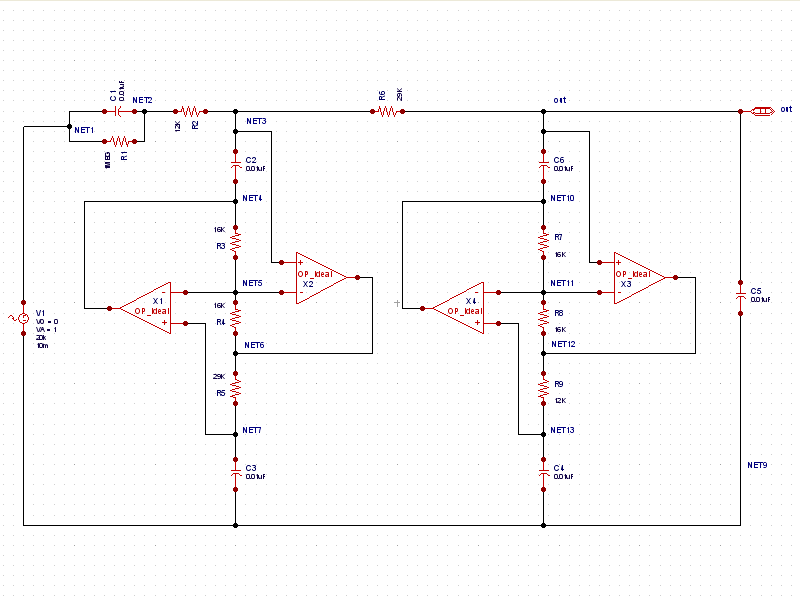
Example 7 is a 4th order lowpass filter design using the Generalized Impedance Converter (GIC) method (see GIC.png pngview). The GIC is practical in active filter design as it uses the Frequency-Dependent Negative Resistor (FDNR) element. This method can effectively simulate circuit elements (ie, inductors) which are difficult to integrate onto the physical chip. The GIC uses active circuit elements and passive impedances to design the low pass filter. In this example, the ideal SPICE opamp model using E elements (voltage-controlled voltage sources). The half-power frequency of this filter is 1KHz.
Clicking on the simulation tab in Gateway reveals the cross probes that are placed on the output node, as shown in cross_probes.png . Here, the phase and dB magnitude responses of the filter are set to be plotted when the simulation finishes.
The Post Process toolbar (see toolbar.png ) contains markers for dropping on schematic wires and pins to save a designated voltage or current. The V/I marker saves a voltage when a marker is dropped on a wire and saves a terminal current when a marker is dropped on a device pin. The second marker from the left is the db marker. In Example 7, this button was pressed and then the wire named OUT was clicked, dropping the VDB(OUT) marker. Next, the third button from the left (phase marker) was pressed, and then the wire marked OUT was clicked again, this time resulting in the VP(OUT) marker being dropped.
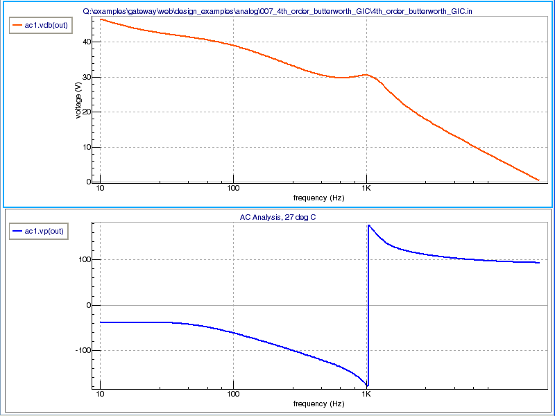
After simulation, the for dB magnitude and phase are shown in the SmartView plots (see output_waveforms.png ).