002_sine2square : Sine to Square Wave Converter
Minimum Required Versions: Gateway 2.12.8.R, SmartSpice 3.16.11.R
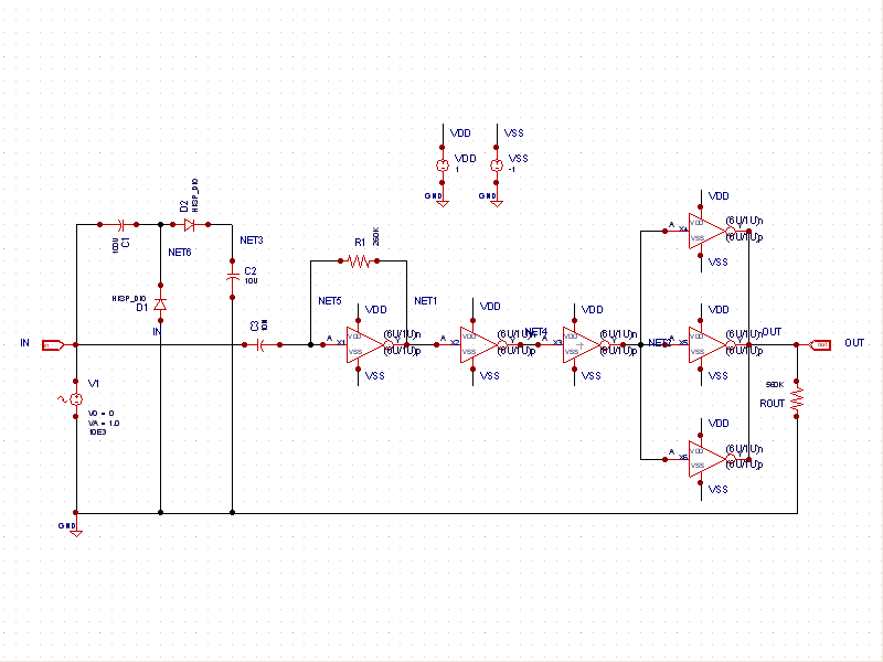
This schematic example (see sine2square.png ) demonstrates a sinusoidal voltage input at a frequency of 10KHz converted to a square wave through an inverter-based circuit. VDD and VSS rails are ties to +1V and =1V, respectively.
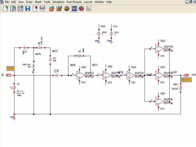
The control file ( sine2square.ctr) contains model statements for the diodes and the MOS devices used by the inverters. By clicking on the Simulation tab in the Library pane, Gateway switches from capture mode to Simulation Mode ( simulation_mode.png ). The voltage markers have been placed on the input node (IN) and the output node (OUT) on the schematic.
After the simulation completes, the waveforms can be displayed (see waveforms.png ).
Input Files
sine2square.ctr
											***** SINE TO SQUARE CONVERTER ****
*
*
*
***** MODELS ******
.model nch nmos level=3
.model pch pmos level=3
.model HISP_DIO D (IS=0.1P RS=12 CJO=1.67P TT=12N BV=100 IBV=3.441E-10)
*
*
*
**** ANALYSIS *****
.tran 5n 0.4ms
*
*
*
.GLOBAL GND VDD VSS
Graphics