002_user_cmd : LISA Script for user-defined Expert commands
Minimum Required Version: Expert 4.10.39.R
As mentioned in the previous example (JavaScript for layout automation), many layout-editing tasks can be automated through the use of scripting. This is especially useful when a certain task needs to be performed repetitively or for a large amount of geometries. One of the methods to increase the efficiency is to apply user-defined commands for such tasks.
Expert offers two choices of scripting language: one is JavaScript, and the other one is LISA (Language for Interfacing SILVACO Applications). This example will show how to generate a user-defined command to:
- Automatically arrange an array of dies on a wafer
- Place verniers and reticles in proper locations
- Set the origin of the whole layout into the geometrical center, through the use of a LISA Script
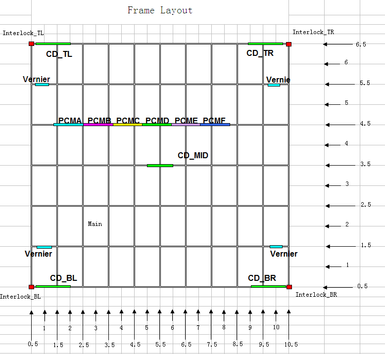
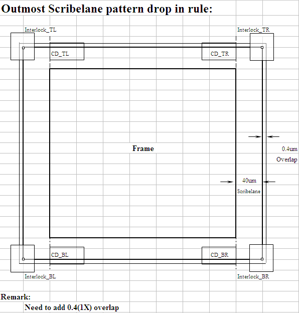
Figure 1 shows the specifications of the die frame. Figure 2 shows additional specifications of scribe lane and overlap.
1.0. Preliminary steps to start example
- Run the Expert application
- Load the "scripting_ex02.eld" project
- Create a new cell layout, in which we will use the new command to generate the frame layout
In the "scripting_ex02.eld" project, there are some existing layout cells: Main layout (the die), Vernier, Interlock, PCM, etc.
1.1. Creating/Loading/Running of the LISA user-defined commands
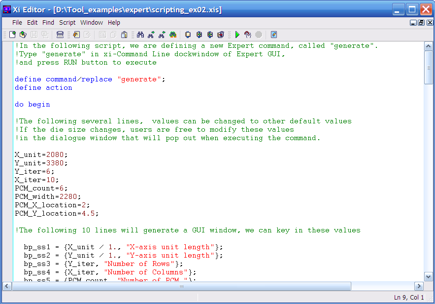
From the Expert window, choose the menu Tool->Script and select LISA. To open the script window, select Tool->Script->Script Panel . In the script window, choose File->Open and select the file scripting_ex02.xis, the script will then appear as shown in Figure 3 .
This script will define a new command called "generate" which will perform the following tasks:
- Provide an input dialog that allows designers to key in the values for necessary parameters
- Generate the Main array (die array), Vernier, Interlock, PCM, etc.
- Produce the extensions for scribe lane and the overlap
- Set the origin of the layout to its geometrical center
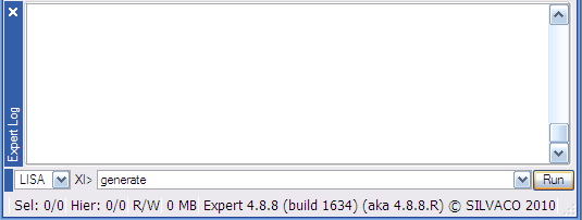
In order to run the script, press the green arrow icon located in the script panel window, or choose Script->Run . The execution of the LISA script defines a new Expert command, called "generate".
Type "generate" in the xi-Command Line dock-window of the Expert GUI, and press RUN to execute, as shown in Figure 4 .
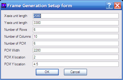
Figure 5 illustrates the input dialog window after the execution of the "generate" command. Figure 6 shows the layout of a 6x10 die array, with properly aligned frame and extension. This layout was generated automatically by the user-defined command. Note that the origin is set to be in the center of the whole layout.
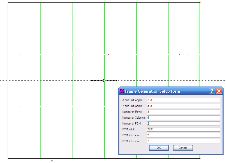
In the dialog window, the user can define the "Number of Rows", "Number of Columns" and "Number of PCM" to be 3, 6 and 2 respectively. These values will lead to the layout of a 3x6 die array , with 2 PCM patterns instead of 6.
1.2 Hints and Tips
- Users can refer to "lisa_users1.pdf" located in "<Silvaco_install_dir>/lib/expert/4.10.39.R/docs/" folder for the details in syntax while creating a LISA Script
- Another useful feature of Expert that can assist in the creation of a LISA Script is the use of the Expert log window ( View->Dock Windows->Expert Log ). This window lists each command performed during the Expert session in the proper LISA (or JavaScript) syntax. Additionally, it provides warning/error messages and the suggestions if there are syntax problem during the compilation.
scripting_ex02.xis
											!In the following script, we are defining a new Expert command, called "generate".
!Type "generate" in xi-Command Line dockwindow of Expert GUI,
!and press RUN button to execute

define command/replace "generate";
define action

do begin

!The following several lines,  values can be changed to other default values
!If the die size changes, users are free to modify these values
!in the dialogue window that will pop out when executing the command.

X_unit=2080;
Y_unit=3380;
Y_iter=6;
X_iter=10;
PCM_count=6;
PCM_width=2280;
PCM_X_location=2;
PCM_Y_location=4.5;

!The following 10 lines will generate a GUI window, we can key in these values

  bp_ss1 = {X_unit / 1., "X-axis unit length"};
  bp_ss2 = {Y_unit / 1., "Y-axis unit length"};
  bp_ss3 = {Y_iter, "Number of Rows"};
  bp_ss4 = {X_iter, "Number of Columns"};
  bp_ss5 = {PCM_count, "Number of PCM "};
  bp_ss6 = {PCM_width / 1., "PCM Width"};
  bp_ss7 = {PCM_X_location / 1., "PCM X location"};
  bp_ss8 = {PCM_Y_location / 1., "PCM Y location"};
  bp_ss = {bp_ss1, bp_ss2, bp_ss3, bp_ss4, bp_ss5, bp_ss6, bp_ss7, bp_ss8};
  sshead1 = {"Frame Generation Setup form"};
  bp_vars = form_create (bp_ss, sshead1);

 X_unit=bp_vars[1];
 Y_unit=bp_vars[2];
 Y_iter=bp_vars[3];
 X_iter=bp_vars[4];
 PCM_count=bp_vars[5];
 PCM_width=bp_vars[6];
 PCM_X_location=bp_vars[7];
 PCM_Y_location=bp_vars[8];

!The following 4 lines will generate the CD_MID pattern in the middle.
!Expert uses cell's origin as the positional input of a instance.

CD_MID_Pos_X = X_unit* (X_iter+1) / 2;
CD_MID_Pos_Y = Y_unit* (Y_iter+1) / 2;
instance (CD_MID_Pos_X) (CD_MID_Pos_Y) /cell = "CD" /name = "CD_MID";
display ("positioning of CD_MID in the middle is done");

!The following 7 statements generate Main array.
!Expert uses first cells's origin as the Array's position.

Main_Pos_X = X_unit* 1;
Main_Pos_Y = Y_unit* 1;
Main_delta_X = X_unit;
Main_delta_Y = Y_unit;
array (Main_Pos_X) (Main_Pos_Y) /cell = "Main"  /row = (Y_iter) /col = (X_iter) /xdeltarow = 0
/ydeltarow = (Main_delta_Y) /xdeltacol = (Main_delta_X) /ydeltacol = 0;
split array (array (Main_Pos_X) (Main_Pos_Y) /cell = "Main"  /row = (Y_iter) /col = (X_iter) /xdeltarow = 0
/ydeltarow = (Main_delta_Y) /xdeltacol = (Main_delta_X) /ydeltacol = 0
 /find /get);
display ("positioning of Main Array is done");

!The scripts below are for generation of Scribelane extention (40um).
scribeline_Pos_X= Main_Pos_X - (X_unit -80) /2 -40;
scribeline_Pos_Y= Main_Pos_Y - (Y_unit -80) /2 -40;
scribeline_Size_X= X_unit * X_iter; !+ 40 * 2;
scribeline_Size_Y= Y_unit * Y_iter; !+ 40 * 2;
box (scribeline_Pos_X) (scribeline_Pos_Y) (scribeline_Size_X) (scribeline_Size_Y) /layer = "Layer2";
display ("positioning of Scribeline extention is done");

!The scripts below are for generation of overlap extention (0.4um).
overlap_Pos_X= Main_Pos_X - (X_unit -80) /2 -40-0.4;
overlap_Pos_Y= Main_Pos_Y - (Y_unit -80) /2 -40-0.4;
overlap_size_X= X_unit * X_iter +  0.4 * 2;
overlap_Size_Y= Y_unit * Y_iter +  0.4 * 2;
box (overlap_Pos_X) (overlap_Pos_Y) (overlap_Size_X) (overlap_Size_Y) /layer = "Layer3";
display ("positioning of overlap extention is done");

!similarly the following 7 lines are for CD_BL, CD_TL, CD_TR, CD_BR array.
CD_Pos_X = X_unit* 1 - (X_unit - 80) / 2 + 1760 / 2;
CD_Pos_Y = Y_unit* 1 - (Y_unit - 80) / 2 - 40 - 0.4 + 35.8 / 2;
CD_delta_X = X_unit * X_iter - 80 - 1760;
CD_delta_Y = Y_unit * Y_iter + 0.4 * 2 -35.8 ;

array (CD_Pos_X) (CD_Pos_Y) /cell = "CD"  /row = 2 /col = 2 /xdeltarow = 0
/ydeltarow = (CD_delta_Y) /xdeltacol = (CD_delta_X) /ydeltacol = 0;
split array (array (CD_Pos_X) (CD_Pos_Y) /cell = "CD"  /row = 2 /col = 2 /xdeltarow = 0
/ydeltarow = (CD_delta_Y) /xdeltacol = (CD_delta_X) /ydeltacol = 0  /find /get);
display ("positioning of CD Array is done");


!similarly the following 7 lines are for vernier array.
Vernier_Pos_X = X_unit* 1 ;
Vernier_Pos_Y = Y_unit* 1.5 ;!- (Y_unit -80 )/ 2 ;
Vernier_delta_X = X_unit * (X_iter -1);
Vernier_delta_Y = Y_unit * (Y_iter -2);

array (Vernier_Pos_X) (Vernier_Pos_Y) /cell = "Vernier"  /row = 2 /col = 2 /xdeltarow = 0
/ydeltarow = (Vernier_delta_Y) /xdeltacol = (Vernier_delta_X) /ydeltacol = 0;
split array (array (Vernier_Pos_X) (Vernier_Pos_Y) /cell = "Vernier"  /row = 2 /col = 2 /xdeltarow = 0
/ydeltarow = (Vernier_delta_Y) /xdeltacol = (Vernier_delta_X) /ydeltacol = 0  /find /get);
display ("positioning of Vernier Array is done");

!similarly the following 7 lines are for Interlock array.
Interlock_Pos_X = X_unit* 0.5 ;
Interlock_Pos_Y = Y_unit* 0.5 ;
Interlock_delta_X = X_unit * X_iter;
Interlock_delta_Y = Y_unit * Y_iter;

array (Interlock_Pos_X) (Interlock_Pos_Y) /cell = "Interlock"  /row = 2 /col = 2 /xdeltarow = 0
/ydeltarow = (Interlock_delta_Y) /xdeltacol = (Interlock_delta_X) /ydeltacol = 0;
split array (array (Interlock_Pos_X) (Interlock_Pos_Y) /cell = "Interlock"  /row = 2 /col = 2 /xdeltarow = 0
/ydeltarow = (Interlock_delta_Y) /xdeltacol = (Interlock_delta_X) /ydeltacol = 0  /find /get);
display ("positioning of Interlock Array is done");


!similarly the following 7 lines are for PCM array.
PCM_Pos_X = X_unit* PCM_X_location ;
PCM_Pos_Y = Y_unit* PCM_Y_location ;
PCM_delta_X = PCM_width;
PCM_delta_Y = 0;

array (PCM_Pos_X) (PCM_Pos_Y) /cell = "PCM"  /row = 1 /col = (PCM_count)
/xdeltarow = 0 /ydeltarow = 0 /xdeltacol = (PCM_delta_X) /ydeltacol = 0;
split array (array (PCM_Pos_X) (PCM_Pos_Y) /cell = "PCM"  /row = 1 /col = (PCM_count)
/xdeltarow = 0 /ydeltarow = 0 /xdeltacol = (PCM_delta_X) /ydeltacol = 0  /find /get);
display ("positioning of PCM Array is done");


!***********************************************************************
! Set cell origin in the center
! Below script seems to be complex, but the mechanism is easy: do a search of objects
! in a given [-32000000, 3200000000] range, and find the smallest rectangle to enclose
! all the objects, set the overal origin of the layout to be the centre of this
! smallest rectangle.
!***********************************************************************
pp1=POINT_CREATE(0,0);

__expert_setup.selectinstances = true;
__expert_setup.selectprimitives = true;

select all;

SEL_OBJS = (find objects (SEARCH_ANY_OBJECT) /selected);
nbr = SEL_OBJS.SIZE;
inst= SEL_OBJS.FIRST;
minX=32000000;
minY=32000000;
maxX=-32000000;
maxY=-32000000;
i = 1;
  loop begin
        Xbbox=inst.bbox.XPOS;
        Ybbox=inst.bbox.YPOS;
        Xtopbox = Xbbox + inst.bbox.XSIZE;
        Ytopbox = Ybbox + inst.bbox.YSIZE;

	if (Xbbox LSS minX) then (minX=Xbbox);
	if (Ybbox LSS minY) then (minY=Ybbox);
	if (Xtopbox GTR maxX) then (maxX=Xtopbox);
	if (Ytopbox GTR maxY) then (maxY=Ytopbox);
        if (i EQL nbr) then (leave loop);
    i = i + 1;
    inst= SEL_OBJS.NEXT;
  end;

pp1.X = (minX + maxX)/2;
pp1.Y = (minY + maxY)/2;
origin (pp1.X) (pp1.Y);

!***********************************************************************

deselect all;

end;

complete command "generate";