008_snap_to_pin : Wire flight lines guide (Snap to pin mode)
Minimum Required Version: Expert 4.10.39.R
When the Snap to pin mode is enabled in the Creating Wires command form, the cursor is automatically snapped to the nearest instance pin to create interconnect wires between the instances. To start and finish creating a wire, select Tools->Snap to pin . This command is best used if assigned to a keyboard shortcut.
When the wire creation is started, a flight line is shown to indicate a destination pin candidate to be connected. If there are multiple candidates, the destination pin can be switched by moving the mouse cursor. Selecting the Tools->Snap to pin command again finishes the wire creation.
Wire stitching can also be performed by enabling the Multipath mode in the Creating Wires command form, provided that technology contacts between the interconnect layers are defined.
When the design is created by schematic-driven layout, the mouse cursor is snapped only to the pins that have the same net name as the first pin. Otherwise, it is snapped to the nearest instance pin.
The actual operation steps are as follows:
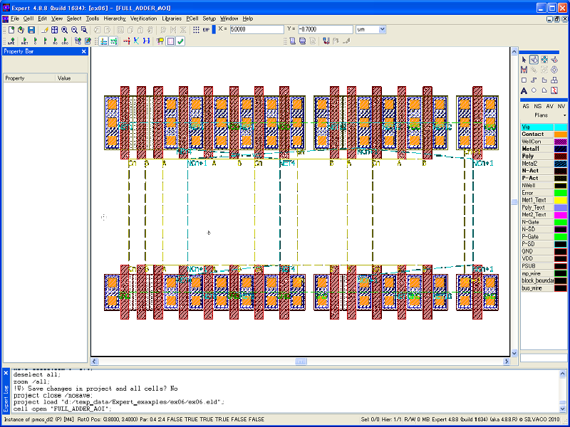
- Select File->Open in the Expert main window to load the project file editing_ex08.eld, and open the top cell FULL_ADDER_AOI (see 1_initial_placement.png ).
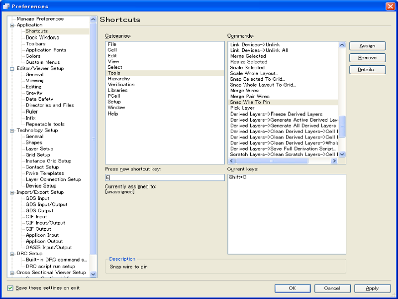
- Select Setup->Editor/Viewer to open the Preferences dialog (see 2_setup_shortcut.png ).
- Open Application->Shortcuts page in the Preferences dialog.
- Select "Tools" in the Categories list, and select "Snap Wire To Pin" in the Commands list.
- In the "Press new shortcut key" text field, type a key combination to assign for the command.
- Click the "Assign" button to validate the shortcut key, and click "OK" button to close the dialog.
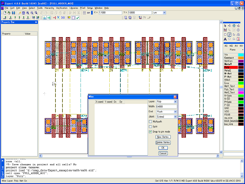
- Select the poly layer in the Layer bar.
- Select Edit->Create Object->Wire command, and press F9 to raise the option form if it doesn't appear.
- Check the "Snap to pin mode" checkbox in the Creating Wires command form.
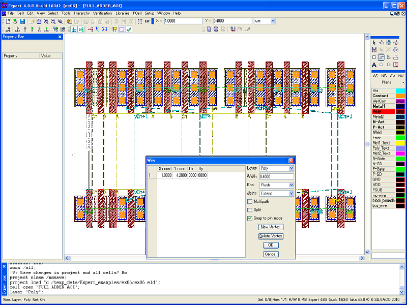
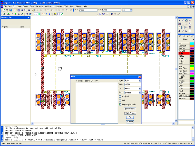
A diamond mark will appear to indicate the nearest MOSFET gate pin to the mouse cursor, to start creating a wire (see 3_before_starting_wire.png ). - Type a shortcut key assigned to the command Tools->Snap to pin to start creating a wire. A flight line will be displayed to the nearest candidate (see 4_starting_wire.png ).
- Type the same shortcut key again to finish the wire creation (see 5_finish_poly_wire.png ).
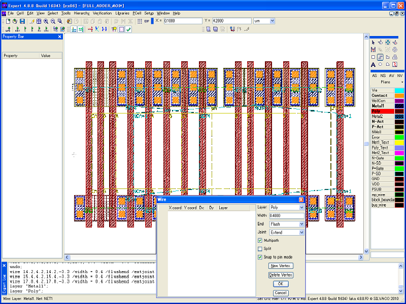
- Create wires for other poly gates as well.
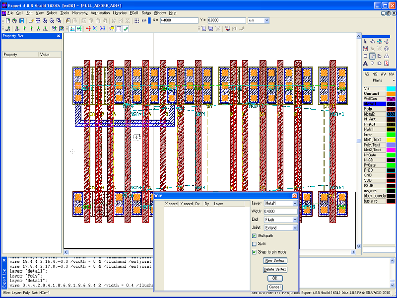
- In the Creating Wires command form, check the "Multipath" checkbox.
A diamond mark will appear to indicate the MOSFET pin, not only in gate, but also in source and drain, nearest to the mouse cursor (see 6_before_starting_metal_wire.png ). - Create a wire in a similar manner as in previous steps (see 7_starting_metal_wire.png and 8_finish_metal_wire.png ).
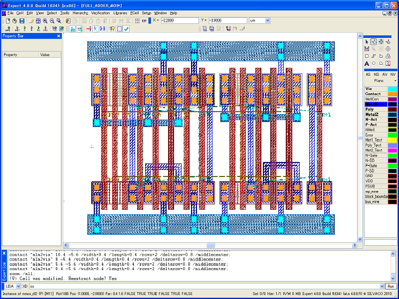
- Create wires for other diffusion pins as well (see 9_finish_all_wires.png ).