004_flight_lines : Wire Flight Lines Guide
Minimum Required Version: Expert 4.10.39.R
When routing an NDL (Netlist Driven Layout) circuit in Expert, using the flight lines tool greatly simplifies the process and can help to verify that all nets are correctly connected. The features of the flight lines tool are illustrated below.
1.0. Preliminary steps to start example
The Expert project "editing_ex04.eld" contains layout for a D-Flip Flop circuit. Once that project is loaded, the cell "DFF_unrouted" can be opened to see the initial placement of all the instances from the NDL netlist of the DFF circuit.
1.1. Displaying Flight Lines
The options for the flight lines can be accessed from the Expert menu Tools->Netlist Driven Layout. To display the flight lines between instance pins, select the menu item Tools->Netlist Driven Layout->Show Nets .
Global nets can be displayed or hidden by selecting Tools->Netlist Driven Layout->Global Nets. These nets will appear in green.
The option Tools->Netlist Driven Layout->Shorted Nets Only will display red flight lines for 2 or more nets that become electrically connected in the layout that were not connected in the NDL netlist.
Flight lines for a net can be hidden after that net is completely routed by selecting Tools->Netlist Driven Layout->Unfinished Nets Only. This feature requires reextraction of connectivity information after any routing is done.
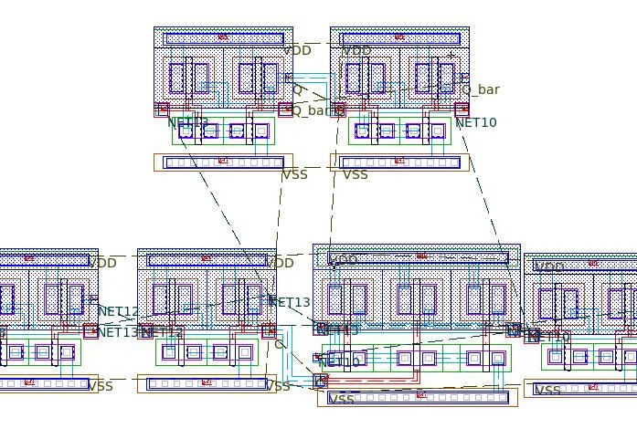
Figure 1 shows the DFF_unrouted cell layout with the options "Show Nets", "Global Nets", and "Show Ports" selected.
1.2. Nets Window
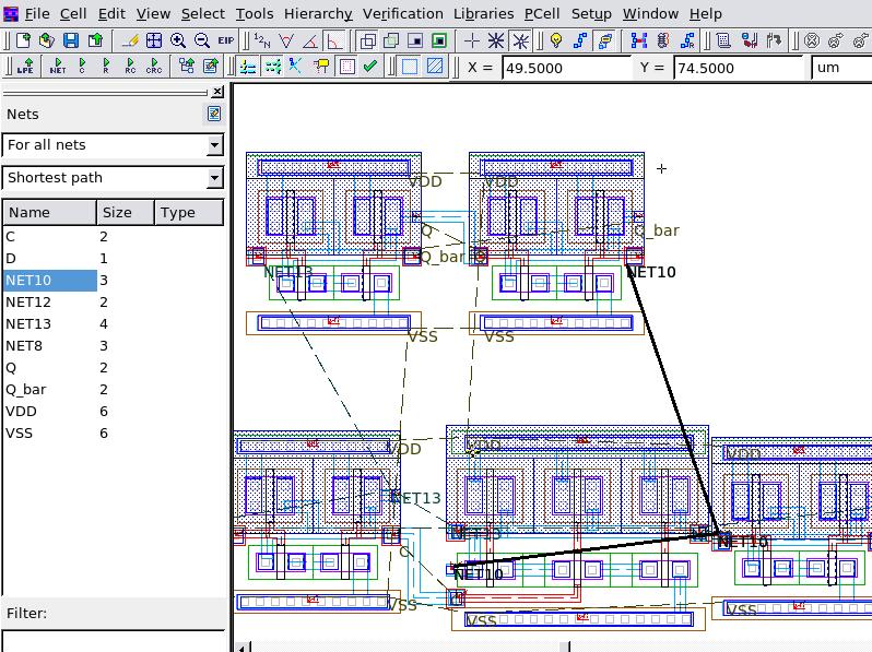
By selecting the menu item View->Dock Windows->Nets , an additional window is opened containing a list of nets for the layout cell. This window contains drop down menus for which nets are visible and how the flight line connections are displayed between pins. The DFF_unrouted cell is seen in Figure 2 with the Nets window activated. An internal net "NET10" is selected in the Nets Window and the corresponding flight line is highlighted in the layout.
1.3. Reextracting Connectivity
The Nets window can aid in monitoring progress during circuit routing by displaying what nets are complete and what nets still have unconnected pins. This is performed by using the menu item Tools->Netlist Driven Layout->Reextract Connectivity . Before this tool is used, the reextraction options must be set by going to Verification->Node Probing->Reextraction Options . Select the options "Prompt for reextraction", "rebuild derived layers on reextraction", and "use dedicated derivation script file", and browse to the editing_ex04_extraction.dsf file.
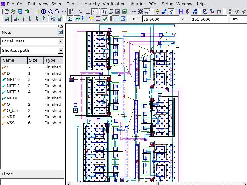
Once the routing of any net is complete, use Reextract Connectivity to update the internal node database and then toggle the option Tools->Netlist Driven Layout->Update Nets and the Nets window will place a check mark next to the nets that are completely routed and mark them as "Finished". Figure 3 shows the completed DFF circuit with the Nets window showing that all nets are routed.
editing_ex04_extraction.dsf
											/* *********************************************************** */
/*                         DRC Script                          */
/*                                    Thu Aug 21 15:09:46 2008 */
/* *********************************************************** */

Layers:
    N_WELL   (42   /* Original */)
,   P_WELL   (59   /* Original */)
,   ACTIVE   (43   /* Original */)
,   THICK_ACTIVE   (60   /* Original */)
,   PBASE   (58   /* Original */)
,   POLY_CAP1   (28   /* Original */)
,   POLY   (46   /* Original */)
,   SILICIDE_BLOCK   (29   /* Original */)
,   N_PLUS_SELECT   (45   /* Original */)
,   P_PLUS_SELECT   (44   /* Original */)
,   POLY2   (56   /* Original */)
,   HI_RES_IMPLANT   (34   /* Original */)
,   CONTACT   (25   /* Original */)
,   METAL1   (49   /* Original */)
,   VIA   (50   /* Original */)
,   METAL2   (51   /* Original */)
,   VIA2   (61   /* Original */)
,   METAL3   (62   /* Original */)
,   VIA3   (30   /* Original */)
,   METAL4   (31   /* Original */)
,   CAP_TOP_METAL   (35   /* Original */)
,   VIA4   (32   /* Original */)
,   METAL5   (33   /* Original */)
,   VIA5   (36   /* Original */)
,   METAL6   (37   /* Original */)
,   DEEP_N_WELL   (38   /* Original */)
,   GLASS   (52   /* Original */)
,   PADS   (26   /* Original */)
,   RES_ID   (1, 0   /* Original */)
,   INDDMY_ID   (2, 0   /* Original */)
;

/*    1 */ free_layer_definition_order: yes;
/*    2 */ Merge_Input: on;
/*    3 */ Database_Precision: 1000;
/*    4 */ Grid_Resolution: GridX = 1, GridY = 1;
/*    5 */ Unit: 1um;
/*    6 */ Incremental_Connect: no;
/*    7 */ Update_layout: input=no, technology=no, new=no, layers=
(pnp_id,pnp_e,pnp_c,npn_e,npn_b,gate,p_sd,n_sd,cmosp_id,cmosn_id,hvcmosp_id,
hvpmos_d,hvnmos_s,rpplus_id,rnpoly_id,rpoly_id,rnwell_id,rpplus_pin,connect_poly,
connect_nwell,substrate,sub_tie,well_tie,deepnwell_tie,p1p2_id,poly_con,poly2cap_con,
ind_id,connect_metal1,ind_plus,ind_minus,NR_counter,width,space,radius
);

Select: Layer1=PBASE, Layer2=N_PLUS_SELECT, LayerR=&PNP_PBASE, Relation=overlap, options=(not);
UnderSize: Value=1um, Layer=&PNP_PBASE, LayerR=&A;
Logicform: pnp_id=&A.dif.(ACTIVE);

Contours: Layer=pnp_id, LayerR=pnp_e, options=(holes);
Logicform: pnp_c=PBASE.and.ACTIVE.dif.(pnp_e.or.P_PLUS_SELECT.or.N_PLUS_SELECT);

Logicform: npn_e=PBASE.and.N_PLUS_SELECT.AND.ACTIVE;
LogicForm: npn_b=PBASE.and.ACTIVE.and.P_PLUS_SELECT;
Logicform: gate=POLY.and.ACTIVE;
Logicform: p_sd=(P_PLUS_SELECT.and.ACTIVE.AND.N_WELL).dif.(POLY.or.DEEP_N_WELL.or.RES_ID);
Logicform: n_sd=(N_PLUS_SELECT.and.ACTIVE).dif.(POLY.or.THICK_ACTIVE.or.N_WELL);
Logicform: cmosp_id=gate.and.P_PLUS_SELECT.and.N_WELL;
Logicform: cmosn_id=gate.and.N_PLUS_SELECT.dif.THICK_ACTIVE;
Logicform: hvcmosp_id=gate.and.P_PLUS_SELECT.and.THICK_ACTIVE.dif.P_WELL;
Select: Layer1=ACTIVE, Layer2=hvcmosp_id, Relation=overlap, LayerR=&A1;
Logicform: hvpmos_d=&A1.dif.(POLY.or.P_WELL.or.N_WELL);
Select: Layer1=ACTIVE, Layer2=hvcmosp_id, Relation=overlap, LayerR=&A2;
Logicform: hvpmos_s=&A2.dif.(hvcmosp_id.or.N_WELL.or.hvpmos_d);
Logicform: hvcmosn_id=gate.and.N_PLUS_SELECT.and.THICK_ACTIVE;
Select: Layer1=ACTIVE, Layer2=hvcmosn_id, Relation=overlap, LayerR=&A3;
Logicform: hvnmos_d=&A3.dif.(POLY.or.P_PLUS_SELECT.or.N_WELL);
Select: Layer1=ACTIVE, Layer2=hvcmosn_id, Relation=overlap, LayerR=&A4;
Logicform: hvnmos_s=&A4.dif.(hvcmosn_id.or.hvnmos_d.or.P_PLUS_SELECT);
Logicform: rpplus_id=N_WELL.and.P_PLUS_SELECT.and.ACTIVE.and.RES_ID;
Logicform: rnpoly_id=N_PLUS_SELECT.and.POLY.and.RES_ID;
Logicform: rpoly_id=(POLY.and.RES_ID).dif.N_PLUS_SELECT;
Logicform: rnwell_id=(N_WELL.and.RES_ID).dif.P_PLUS_SELECT;
LogicForm: &rpplus_pin1=(ACTIVE.and.P_PLUS_SELECT).dif.RES_ID;
Select: Relation=touch, Layer1=&rpplus_pin1, Layer2=rpplus_id, LayerR=rpplus_pin;
Logicform: connect_poly=POLY.dif.(RES_ID.or.POLY2);
Logicform: connect_nwell=N_WELL.dif.(RES_ID);
Substrate: LayerR=substrate;
Logicform: sub_tie=(ACTIVE.AND.P_PLUS_SELECT).dif.(DEEP_N_WELL.or.N_WELL);
Logicform: well_tie=(ACTIVE.AND.N_PLUS_SELECT.AND.N_WELL).dif.npn_e;
Logicform: &deepnwell_tie1=ACTIVE.AND.N_PLUS_SELECT.AND.DEEP_N_WELL;
Select: Relation=touch, Layer1=&deepnwell_tie1, Layer2=hvpmos_s, LayerR=&tempA;
LogicForm: deepnwell_tie=&deepnwell_tie1.dif.&tempA;
Logicform: p1p2_id=(POLY2.and.POLY).dif.ACTIVE;
Logicform: poly_con=(POLY.dif.POLY2).and.CONTACT;
Logicform: poly2cap_con=POLY.AND.POLY2.and.CONTACT;

LogicForm: &ind_id1=METAL1.and.INDDMY_ID;
PERIMETER: Layer=&ind_id1, Value=75, Type=GT, LayerR=ind_id;
select: relation=vertex, Layer=METAL1, Options=(5:99999), LayerR=&metal1;
//LogicForm: connect_metal1=&metal1.dif.ind_id;
Corner: Layer=ind_id, Value=0.1, Options=(INSIDE,A90),LayerR=&temp11;
Select: Relation=flush, Layer1=&temp11, Layer2=INDDMY_ID, LayerR=&temp2;
Size: Layer=&temp2, within=ind_id, Options=(cut), step=0.5, Value=10, LayerR=ind_plus;
Corner: Layer=ind_id, Value=0.2, Options=(inside,A90), LayerR=&temp12;
Size: Layer=&temp12, within=ind_id, Options=(cut), step=0.5, Value=10, LayerR=&temp;
//Select: Relation=flush, Layer1=&temp, Layer2=INDDMY_ID, LayerR=ind_minus, Options=(not);
//Added new by AK 09/10/08
Select: Relation=vertex, Layer=&ind_id1, Options=(1:4), LayerR=&ind_minus1;
LogicForm: ind_minus2=METAL2.and.INDDMY_ID.and.&ind_minus1;
LogicForm: connect_metal1=(METAL1.dif.ind_id); //so that the 4-vertex M1 piece inside INDDMY will also get connectivity
Select: Relation=overlap, Layer1=METAL2, Layer2=ind_id, LayerR=ind_minus;


//New code ends

Corner: Layer=ind_id, Value=0.1, Options=(inside,any), LayerR=NR_counter;
LogicForm: width=(METAL1.and.METAL2.and.INDDMY_ID).dif.ind_minus2;
LogicForm: &space1=(METAL2.and.INDDMY_ID).dif.METAL1;
PERIMETER: Layer=&space1, LayerR=&space2, Value=79, Type=LT;
SELECT: Relation=touch, layer1=&space2, Layer2=ind_id, LayerR=&space3;
SELECT_edges: Relation=coincide, layer1=&space3, Layer2=ind_id, LayerR=&space4;
SELECT: Relation=touch, layer1=&space3, Layer2=&space4, LayerR=space, options=(2:2);
LogicForm: &space1A=(METAL2.and.INDDMY_ID).dif.METAL1;
PERIMETER: Layer=&space1A, LayerR=radius, Value=80, Type=GE;