
Simulation Standard Technical Journal
A Journal for Process and Device Engineers
 https://silvaco.com/wp-content/uploads/2026/04/SS_Q2_APR2026.jpg
328
250
Gigi Boss
/wp-content/uploads/2019/11/silvaco-logo.png
Gigi Boss2026-04-27 11:55:432026-04-28 15:12:41Accelerating Next-Generation Power Technologies with AI-Powered FTCO
https://silvaco.com/wp-content/uploads/2026/04/SS_Q2_APR2026.jpg
328
250
Gigi Boss
/wp-content/uploads/2019/11/silvaco-logo.png
Gigi Boss2026-04-27 11:55:432026-04-28 15:12:41Accelerating Next-Generation Power Technologies with AI-Powered FTCO https://silvaco.com/wp-content/uploads/2026/03/SS_Q1_MAR2026.png
324
250
Gigi Boss
/wp-content/uploads/2019/11/silvaco-logo.png
Gigi Boss2026-03-19 10:24:562026-04-27 12:15:57Organic Transport Model for Tandem Organic Light-Emitting Diode
https://silvaco.com/wp-content/uploads/2026/03/SS_Q1_MAR2026.png
324
250
Gigi Boss
/wp-content/uploads/2019/11/silvaco-logo.png
Gigi Boss2026-03-19 10:24:562026-04-27 12:15:57Organic Transport Model for Tandem Organic Light-Emitting Diode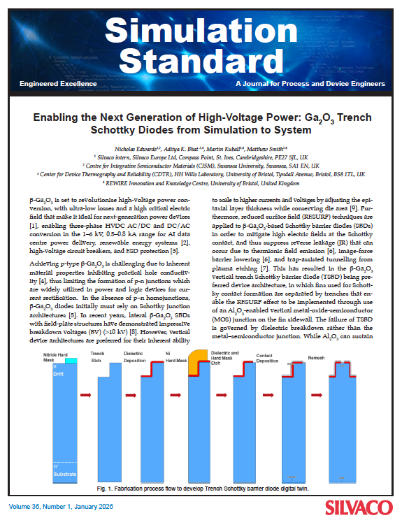 https://silvaco.com/wp-content/uploads/2026/01/SS_Q1_JAN2026.png
754
575
Gigi Boss
/wp-content/uploads/2019/11/silvaco-logo.png
Gigi Boss2026-01-20 14:14:132026-04-27 12:19:29Enabling the Next Generation of High-Voltage Power: Gallium Oxide Trench Schottky Diodes from Simulation to System
https://silvaco.com/wp-content/uploads/2026/01/SS_Q1_JAN2026.png
754
575
Gigi Boss
/wp-content/uploads/2019/11/silvaco-logo.png
Gigi Boss2026-01-20 14:14:132026-04-27 12:19:29Enabling the Next Generation of High-Voltage Power: Gallium Oxide Trench Schottky Diodes from Simulation to System https://silvaco.com/wp-content/uploads/2025/12/SS_Q4_DEC2025.png
330
250
Gigi Boss
/wp-content/uploads/2019/11/silvaco-logo.png
Gigi Boss2025-12-18 11:30:202025-12-18 11:53:33Victory TCAD 2025 Release
https://silvaco.com/wp-content/uploads/2025/12/SS_Q4_DEC2025.png
330
250
Gigi Boss
/wp-content/uploads/2019/11/silvaco-logo.png
Gigi Boss2025-12-18 11:30:202025-12-18 11:53:33Victory TCAD 2025 Release https://silvaco.com/wp-content/uploads/2025/11/SS_Q4_NOV2025.jpg
329
250
Gigi Boss
/wp-content/uploads/2019/11/silvaco-logo.png
Gigi Boss2025-11-17 15:15:492025-12-01 13:40:01Accelerating Vertical GaN Power Technology Development with Physics-based Digital Twins for 800V DC AI Factory Power Infrastructure
https://silvaco.com/wp-content/uploads/2025/11/SS_Q4_NOV2025.jpg
329
250
Gigi Boss
/wp-content/uploads/2019/11/silvaco-logo.png
Gigi Boss2025-11-17 15:15:492025-12-01 13:40:01Accelerating Vertical GaN Power Technology Development with Physics-based Digital Twins for 800V DC AI Factory Power Infrastructure https://silvaco.com/wp-content/uploads/2025/09/SS_Q3_SEP2025.jpg
318
250
Gigi Boss
/wp-content/uploads/2019/11/silvaco-logo.png
Gigi Boss2025-09-19 10:51:362025-09-26 11:54:00Dynamic Testing for Power MOSFET
https://silvaco.com/wp-content/uploads/2025/09/SS_Q3_SEP2025.jpg
318
250
Gigi Boss
/wp-content/uploads/2019/11/silvaco-logo.png
Gigi Boss2025-09-19 10:51:362025-09-26 11:54:00Dynamic Testing for Power MOSFET