003_freq_divider : RF Frequency Divider Schematic Simulation
Minimum Required Versions: Gateway 2.12.8.R, SmartSpiceRF 1.6.3.R
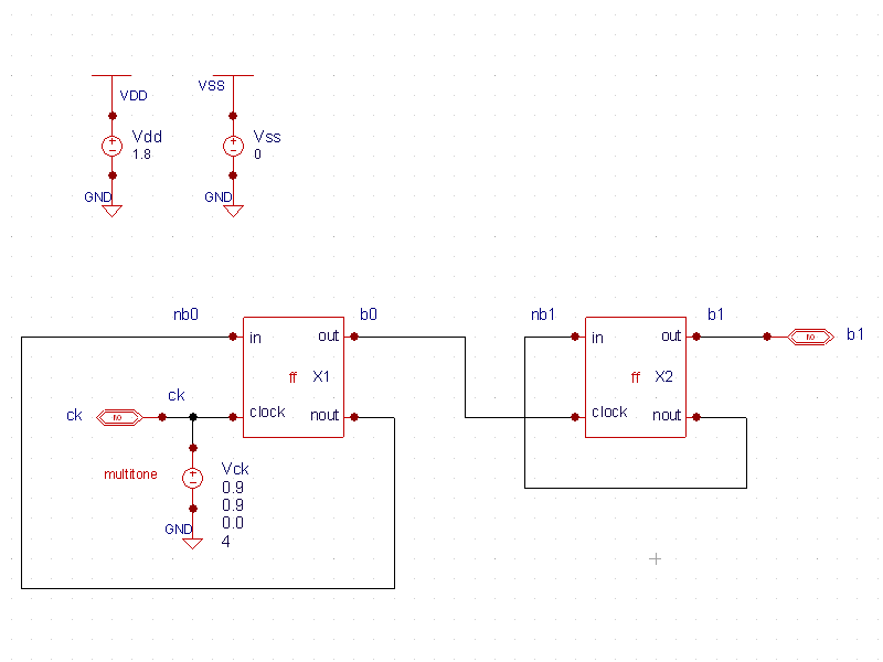
The schematic for Example 3 ( schematic.png ) is a frequency divider design. Since the division factor is 4, the fundamental frequency is set to the output frequency (FUND1=250MegHz) equal to the input frequency (1 GHz) divided by 4. RF input source at 4*FUND1frequency is specified as fourth harmonic stimuli: Vck ck GND DC 0.9 MTS1(0.9 0.0 4) .
In the control file ( freq_divider.ctr), a large number of harmonics (nharm1=40) and an oversampling factor of 2 (oversample=2) are specified to better represent the square-like waveforms produced by this nonlinear circuit.
A Transient Initial Guess (TIG) is set by UseTIG=3. Transient simulation time is defined by TIGtstop=5n. The accuracy option reltol=1e-6 is set to obtain an accurate initial guess.
The quality of the initial guess can be determined by checking the first Newton KCL residual (displayed with annotate=4). The lower the residual numerical value, the better is the initial guess.
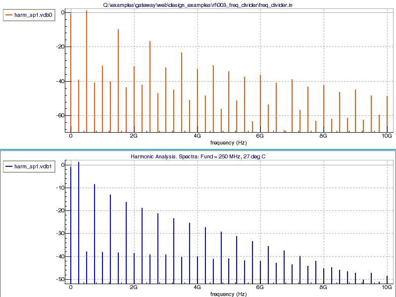
The .IPLOT harm_sp vdb0 vdb1 statement is used to interactively plot the spectra for b0 and b1 as the simulation runs. The resulting plot is shown in SmartView ( spectra.png ).
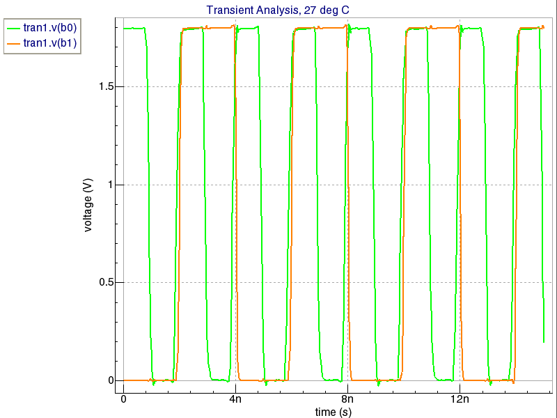
Expanding the transient analysis in the data browser, the waveforms are plotted for nodes b0 and b1 ( transient.png ).
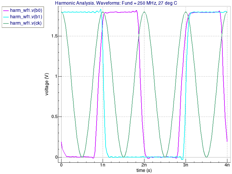
Finally, the RF input stimulus, the RF voltage waveform at node b0 (division by 2), and the RF voltage waveform at node b1 (division by 4) are seen on the RF plot ( RF.png ).
freq_divider.ctr
											* BSIM4v6 Frequency Devider/4 for HARMONIC analysis
*
.options nomod acct=2  reltol=1e-6
.global vss vdd
*
*
.HARM FUND1=250MegHz nharm1=40
+ oversample = 2
+ UseTIG = 3
+ TIGtstop = 15n
+ TIGtmax = 0.1n
+ annotate=4
+ waves
*
* Results
.PROBE v(ck) v(b0) v(b1)
.LET harm_sp vdb0='db(v(b0))' vdb1='db(v(b1))'
.IPLOT harm_sp vdb0 vdb1
*
** Model: BSIM4.6.0
** Berkeley SPICE3f5 Compatible
** Lmin=0.02 Lmax=10 Wmin=0.6 Wmax=20

.MODEL NCH  NMOS  LEVEL = 14
+VERSION = 6.0          BINUNIT = 1            PARAMCHK= 1            MOBMOD  = 0
+CAPMOD  = 2            IGCMOD  = 1            IGBMOD  = 1            GEOMOD  = 1
+DIOMOD  = 1            RDSMOD  = 0            RBODYMOD= 0            RGATEMOD= 1
+PERMOD  = 1            ACNQSMOD= 0            TRNQSMOD= 0            TEMPMOD = 0

+TNOM    = 27           TOXE    = 1.8E-009     TOXP    = 10E-010      TOXM    = 1.8E-009
+DTOX    = 8E-10        EPSROX  = 3.9          WINT    = 5E-009       LINT    = 1E-009
+LL      = 0            WL      = 0            LLN     = 1            WLN     = 1
+LW      = 0            WW      = 0            LWN     = 1            WWN     = 1
+LWL     = 0            WWL     = 0            XPART   = 0            TOXREF  = 1.4E-009

+SAREF   = 5E-6         SBREF   = 5E-6         WLOD    = 2E-6         KU0     = -4E-6
+KVSAT   = 0.2          KVTH0   = -2E-8        TKU0    = 0.0          LLODKU0 = 1.1
+WLODKU0 = 1.1          LLODVTH = 1.0  	       WLODVTH = 1.0 	      LKU0    = 1E-6
+WKU0	 = 1E-6  	PKU0    = 0.0  	       LKVTH0  = 1.1E-6       WKVTH0  = 1.1E-6
+PKVTH0  = 0.0  	STK2    = 0.0          LODK2   = 1.0          STETA0  = 0.0
+LODETA0 = 1.0
+LAMBDA  = 4E-10
+VSAT    = 1.1E+005
+VTL	 = 2.0E5 	XN	= 6.0 	       LC      = 5E-9
+RNOIA   = 0.577 	RNOIB   = 0.37
+LINTNOI = 1E-009
+TVOFF	 = 0.0		TVFBSDOFF = 0.0
+VTH0    = 0.25
+K1      = 0.35         K2      = 0.05         K3      = 0
+K3B     = 0            W0      = 2.5E-006     DVT0    = 1.8          DVT1    = 0.52
+DVT2    = -0.032       DVT0W   = 0            DVT1W   = 0            DVT2W   = 0
+DSUB    = 2            MINV    = 0.05         VOFFL   = 0            DVTP0   = 1E-007
+DVTP1   = 0.05         LPE0    = 5.75E-008    LPEB    = 2.3E-010     XJ      = 2E-008
+NGATE   = 5E+020       NDEP    = 2.8E+018     NSD     = 1E+020       PHIN    = 0
+CDSC    = 0.0002       CDSCB   = 0            CDSCD   = 0            CIT     = 0
+VOFF    = -0.15        NFACTOR = 1.2          ETA0    = 0.05         ETAB    = 0
+UC      = -3E-011
+VFB     = -0.55        U0      = 0.032        UA      = 5.0E-011     UB      = 3.5E-018
+A0      = 2            AGS     = 1E-020
+A1      = 0            A2      = 1            B0      = -1E-020      B1      = 0
+KETA    = 0.04         DWG     = 0            DWB     = 0            PCLM    = 0.08
+PDIBLC1 = 0.028        PDIBLC2 = 0.022        PDIBLCB = -0.005       DROUT   = 0.45
+PVAG    = 1E-020       DELTA   = 0.01         PSCBE1  = 8.14E+008    PSCBE2  = 5E-008
+FPROUT  = 0.2          PDITS   = 0.2          PDITSD  = 0.23         PDITSL  = 2.3E+006
+RSH     = 0            RDSW    = 50           RSW     = 50           RDW     = 50
+RDSWMIN = 0            RDWMIN  = 0            RSWMIN  = 0            PRWG    = 0
+PRWB    = 6.8E-011     WR      = 1            ALPHA0  = 0.074        ALPHA1  = 0.005
+BETA0   = 30           AGIDL   = 0.0001       BGIDL   = 2.1E+009     CGIDL   = 0.0001
+EGIDL   = 0.8          AGISL   = 0.0002       BGISL   = 2.1E+009     CGISL   = 0.0002
+EGISL   = 0.8

+AIGBACC = 0.012        BIGBACC = 0.0028       CIGBACC = 0.002
+NIGBACC = 1            AIGBINV = 0.014        BIGBINV = 0.004        CIGBINV = 0.004
+EIGBINV = 1.1          NIGBINV = 3            AIGC    = 0.012        BIGC    = 0.0028
+CIGC    = 0.002        AIGS    = 0.012        BIGS    = 0.0028       CIGS    = 0.002
+NIGC    = 1            POXEDGE = 1            PIGCD   = 1            NTOX    = 1
+AIGD	 = 0.01		BIGD	= 0.003	       CIGD    = 0.0015

+XRCRG1  = 12           XRCRG2  = 5
+CGSO    = 6.238E-010   CGDO    = 6.238E-010   CGBO    = 2.56E-011    CGDL    = 2.495E-10
+CGSL    = 2.495E-10    CKAPPAS = 0.03         CKAPPAD = 0.03         ACDE    = 1
+MOIN    = 15           NOFF    = 0.9          VOFFCV  = 0.02

+KT1     = -0.37        KT1L    = 0.0           KT2     = -0.042       UTE     = -1.5
+UA1     = 1E-009       UB1     = -3.5E-019     UC1     = 0            PRT     = 0
+AT      = 53000

+FNOIMOD = 1            TNOIMOD = 0

+JSS     = 0.0001       JSWS    = 1E-011       JSWGS   = 1E-010       NJS     = 1
+IJTHSFWD= 0.01         IJTHSREV= 0.001        BVS     = 10           XJBVS   = 1
+JSD     = 0.0001       JSWD    = 1E-011       JSWGD   = 1E-010       NJD     = 1
+IJTHDFWD= 0.01         IJTHDREV= 0.001        BVD     = 10           XJBVD   = 1
+PBS     = 1            CJS     = 0.0005       MJS     = 0.5          PBSWS   = 1
+CJSWS   = 5E-010       MJSWS   = 0.33         PBSWGS  = 1            CJSWGS  = 3E-010
+MJSWGS  = 0.33         PBD     = 1            CJD     = 0.0005       MJD     = 0.5
+PBSWD   = 1            CJSWD   = 5E-010       MJSWD   = 0.33         PBSWGD  = 1
+CJSWGD  = 5E-010       MJSWGD  = 0.33         TPB     = 0.005        TCJ     = 0.001
+TPBSW   = 0.005        TCJSW   = 0.001        TPBSWG  = 0.005        TCJSWG  = 0.001
+XTIS    = 3            XTID    = 3

+DMCG    = 0E-006       DMCI    = 0E-006       DMDG    = 0E-006       DMCGT   = 0E-007
+DWJ     = 0.0E-008     XGW     = 0E-007       XGL     = 0E-008

+RSHG    = 0.4          GBMIN   = 1E-010       RBPB    = 5            RBPD    = 15
+RBPS    = 15           RBDB    = 15           RBSB    = 15           NGCON   = 1

+JTSS    = 1E-4         JTSD    = 1E-4         JTSSWS  = 1E-10        JTSSWD = 1E-10
+JTSSWGS = 1E-7         JTSSWGD = 1E-7
+NJTS    = 20.0         NJTSSW  = 15           NJTSSWG = 6            VTSS   = 10
+VTSD    = 10           VTSSWS  = 10           VTSSWD  = 10
+NJTSD   = 15.0         NJTSSWD  = 20          NJTSSWGD = 6
+TNJTS   = 0.1          TNJTSD  = 0.05
+VTSSWGS=2 VTSSWGD=2
+XTSS = 0.02 XTSD = 0.02 XTSSWS = 0.02 XTSSWD = 0.02 XTSSWGS = 0.02 XTSSWGD = 0.02

** Model: BSIM4.6.0
** Berkeley SPICE3f5 Compatible
** Lmin=0.02 Lmax=10 Wmin=0.6 Wmax=20

.MODEL  PCH  PMOS  LEVEL = 14
+VERSION = 6.0          BINUNIT = 1            PARAMCHK= 1            MOBMOD  = 0
+CAPMOD  = 2            IGCMOD  = 1            IGBMOD  = 1            GEOMOD  = 1
+DIOMOD  = 1            RDSMOD  = 0            RBODYMOD= 0            RGATEMOD= 1
+PERMOD  = 1            ACNQSMOD= 0            TRNQSMOD= 0            TEMPMOD = 0

+TNOM    = 27           TOXE    = 1.8E-009     TOXP    = 10E-010      TOXM    = 1.8E-009
+DTOX    = 8E-10        EPSROX  = 3.9          WINT    = 5E-009       LINT    = 1E-009
+LL      = 0            WL      = 0            LLN     = 1            WLN     = 1
+LW      = 0            WW      = 0            LWN     = 1            WWN     = 1
+LWL     = 0            WWL     = 0            XPART   = 0            TOXREF  = 1.8E-9

+SAREF   = 5E-6         SBREF   = 5E-6         WLOD    = 2E-6         KU0     = 4E-6
+KVSAT   = 0.2          KVTH0   = -2E-8        TKU0    = 0.0          LLODKU0 = 1.1
+WLODKU0 = 1.1          LLODVTH = 1.0  	       WLODVTH = 1.0 	      LKU0    = 1E-6
+WKU0	 = 1E-6  	PKU0    = 0.0  	       LKVTH0  = 1.1E-6       WKVTH0  = 1.1E-6
+PKVTH0  = 0.0  	STK2    = 0.0          LODK2   = 1.0          STETA0  = 0.0
+LODETA0 = 1.0
+LAMBDA  = 4E-10
+VSAT    = 1.1E+005
+VTL	 = 2.0E5 	XN	= 6.0 	       LC      = 5E-9
+RNOIA   = 0.577 	RNOIB   = 0.37
+LINTNOI = 1E-009
+TVOFF   = 0.0          TVFBSDOFF = 0.0
+VTH0    = -0.25
+K1      = 0.35         K2      = 0.05         K3      = 0
+K3B     = 0            W0      = 2.5E-006     DVT0    = 1.8          DVT1    = 0.52
+DVT2    = -0.032       DVT0W   = 0            DVT1W   = 0            DVT2W   = 0
+DSUB    = 2            MINV    = 0.05         VOFFL   = 0            DVTP0   = 1E-007
+DVTP1   = 0.05         LPE0    = 5.75E-008    LPEB    = 2.3E-010     XJ      = 2E-008
+NGATE   = 5E+020       NDEP    = 2.8E+018     NSD     = 1E+020       PHIN    = 0
+CDSC    = 0.0002       CDSCB   = 0            CDSCD   = 0            CIT     = 0
+VOFF    = -0.15        NFACTOR = 1.2          ETA0    = 0.05         ETAB    = 0
+VFB     =  0.55        U0      = 0.0095       UA      = 5.0E-011     UB      = 3.5E-018
+UC      = -3E-011
+A0      = 2            AGS     = 1E-020
+A1      = 0            A2      = 1            B0      = -1E-020      B1      = 0
+KETA    = 0.04         DWG     = 0            DWB     = 0            PCLM    = 0.08
+PDIBLC1 = 0.028        PDIBLC2 = 0.022        PDIBLCB = -0.005       DROUT   = 0.45
+PVAG    = 1E-020       DELTA   = 0.01         PSCBE1  = 8.14E+008    PSCBE2  = 5E-008
+FPROUT  = 0.2          PDITS   = 0.2          PDITSD  = 0.23         PDITSL  = 2.3E+006
+RSH     = 0            RDSW    = 50           RSW     = 50           RDW     = 50
+RDSWMIN = 0            RDWMIN  = 0            RSWMIN  = 0            PRWG    = 0
+PRWB    = 6.8E-011     WR      = 1            ALPHA0  = 0.074        ALPHA1  = 0.005
+BETA0   = 30           AGIDL   = 0.0002       BGIDL   = 2.1E+009     CGIDL   = 0.0002
+EGIDL   = 0.8          AGISL   = 0.0003       BGISL   = 2.5E+009     CGISL   = 0.0003
+EGISL   = 0.8

+AIGBACC = 0.012        BIGBACC = 0.0028       CIGBACC = 0.002
+NIGBACC = 1            AIGBINV = 0.014        BIGBINV = 0.004        CIGBINV = 0.004
+EIGBINV = 1.1          NIGBINV = 3            AIGC    = 0.012        BIGC    = 0.0028
+CIGC    = 0.002        AIGS    = 0.012        BIGS    = 0.0028       CIGS    = 0.002
+NIGC    = 1            POXEDGE = 1            PIGCD   = 1            NTOX    = 1
+AIGD    = 0.01         BIGD    = 0.003        CIGD    = 0.0015

+XRCRG1  = 12           XRCRG2  = 5
+CGSO    = 6.238E-010   CGDO    = 6.238E-010   CGBO    = 2.56E-011    CGDL    = 2.495E-10
+CGSL    = 2.495E-10    CKAPPAS = 0.03         CKAPPAD = 0.03         ACDE    = 1
+MOIN    = 15           NOFF    = 0.9          VOFFCV  = 0.02

+KT1     = -0.37        KT1L    = 0.0           KT2     = -0.042       UTE     = -1.5
+UA1     = 1E-009       UB1     = -3.5E-019     UC1     = 0            PRT     = 0
+AT      = 53000

+FNOIMOD = 1            TNOIMOD = 0

+JSS     = 0.0001       JSWS    = 1E-011       JSWGS   = 1E-010       NJS     = 1
+IJTHSFWD= 0.01         IJTHSREV= 0.001        BVS     = 10           XJBVS   = 1
+JSD     = 0.0001       JSWD    = 1E-011       JSWGD   = 1E-010       NJD     = 1
+IJTHDFWD= 0.01         IJTHDREV= 0.001        BVD     = 10           XJBVD   = 1
+PBS     = 1            CJS     = 0.0005       MJS     = 0.5          PBSWS   = 1
+CJSWS   = 5E-010       MJSWS   = 0.33         PBSWGS  = 1            CJSWGS  = 3E-010
+MJSWGS  = 0.33         PBD     = 1            CJD     = 0.0005       MJD     = 0.5
+PBSWD   = 1            CJSWD   = 5E-010       MJSWD   = 0.33         PBSWGD  = 1
+CJSWGD  = 5E-010       MJSWGD  = 0.33         TPB     = 0.005        TCJ     = 0.001
+TPBSW   = 0.005        TCJSW   = 0.001        TPBSWG  = 0.005        TCJSWG  = 0.001
+XTIS    = 3            XTID    = 3

+DMCG    = 0E-006       DMCI    = 0E-006       DMDG    = 0E-006       DMCGT   = 0E-007
+DWJ     = 0.0E-008     XGW     = 0E-007       XGL     = 0E-008

+RSHG    = 0.4          GBMIN   = 1E-010       RBPB    = 5            RBPD    = 15
+RBPS    = 15           RBDB    = 15           RBSB    = 15           NGCON   = 1

+JTSS    = 1E-4         JTSD    = 1E-4         JTSSWS  = 1E-10        JTSSWD = 1E-10
+JTSSWGS = 1E-7         JTSSWGD = 1E-7
+NJTS    = 20.0         NJTSSW  = 15           NJTSSWG = 4            VTSS   = 10
+VTSD    = 10           VTSSWS  = 10           VTSSWD  = 10
+NJTSD   = 15.0         NJTSSWD  = 20          NJTSSWGD = 6
+TNJTS   = 0.1          TNJTSD  = 0.05
+VTSSWGS=2 VTSSWGD=2
+XTSS = 0.02 XTSD = 0.02 XTSSWS = 0.02 XTSSWD = 0.02 XTSSWGS = 0.02 XTSSWGD = 0.02
*