001_LNA : LNA schematic RF Simulation
Minimum Required Versions: Gateway 2.12.8.R, SmartSpiceRF 1.6.3.R
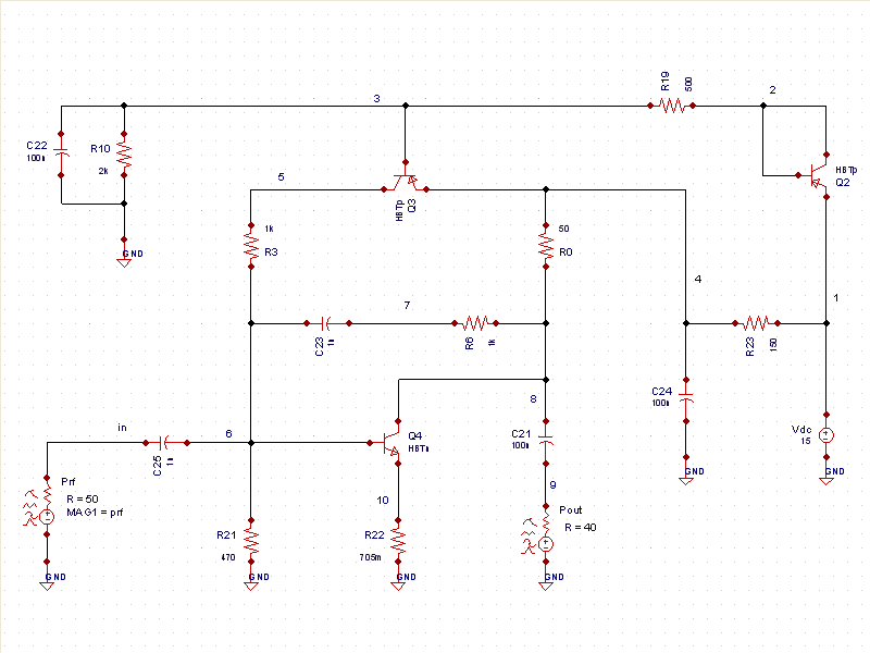
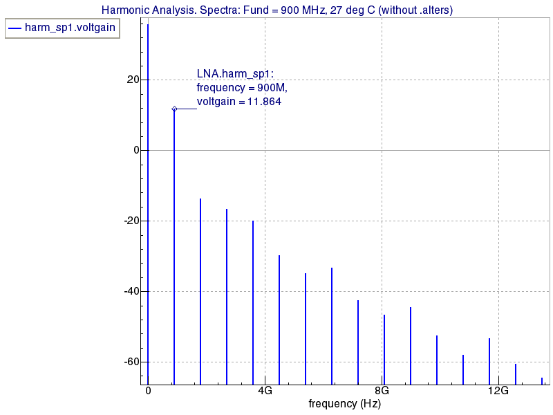
Typical Low Noise Amplifier (LNA) designs utilize reasonable gain and a low noise figure to provide stability without oscillation over the useful range of frequencies (see LNA.png ). Often used in receiver designs, LNAs amplify extremely low signals without adding noise, ensuring the required SNR at low power. In Gateway, set the simulator to SmartSpiceRF. The RF control file for this design ( LNA.ctr) is opened by choosing Simulation->Edit Control File from the main menus. The .ALTER statement and all statements following it are run after the first simulation has completed. Following the first simulation, drag the 'voltgain' vector from the harm_sp1 analysis in Smartview out into the plot areai ( spectralplot.png ). Looking at the spectral plot, the gain at 900MHz is 11.864dB.
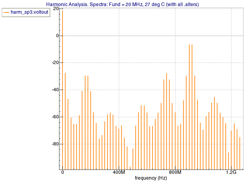
The second simulation shows output voltage distribution. The plot.png shows voltage spikes at 20MHz, 900MHz, and 920MHz.
LNA.ctr
											* VoltGain


.param prf=-10_dBm
.param rpar21=470

$ ----------- Voltage Gain ------------
.HARM
+  FUND=900MegHz nharm=15
+  annotate=3 waves

.MEASURE HARM_SP modH1in FIND vm(in) AT=900MegHz  $ 1.3547e-01
.MEASURE HARM_SP modH1out FIND vm(8) AT=900MegHz
.MEASURE HARM_SP GAIN EXPR VAL='db20(modH1out/modH1in)'

.let HARM_SP VoltGain='db(vm(8)/1.3547e-01)'

* Low-Noise Amplifier

.OPTION NOMOD ACCT POST

.param kfn = 1.e-24 sh = 0

.include HBT1.mod

.ALTER
.param prf=-10_dBm
.param rpar21=470

Pout 9  0  r=40
Prf  in 0
+    MTS1=(prf 0 45) MTS2=(prf 0 46)
* OutputVoltDistribution
$ ----------------------
.HARM
+  FUND=20MegHz nharm=63
+  annotate=3 waves

.let HARM_SP VoltOut='vdb(8)'
.MEASURE HARM_SP sp20  FIND VoltOut AT=20MegHz
.MEASURE HARM_SP sp900 FIND VoltOut AT=900MegHz
.MEASURE HARM_SP sp920 FIND VoltOut AT=920MegHz